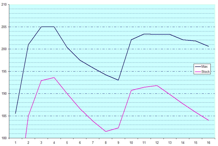
I've been enjoying Black Cat at around 198ḞF.
Thanks for documenting.
Cheers,
Fred
The pot allows the user to adjust the temperature above 200ḞF. The LED indicates the heater element is ON. When it goes out, the boiler is at the set temperature.
These mods are not difficult. IF you've never soldered a PCB or wired anything, try to find a friend who has. PLEASE!
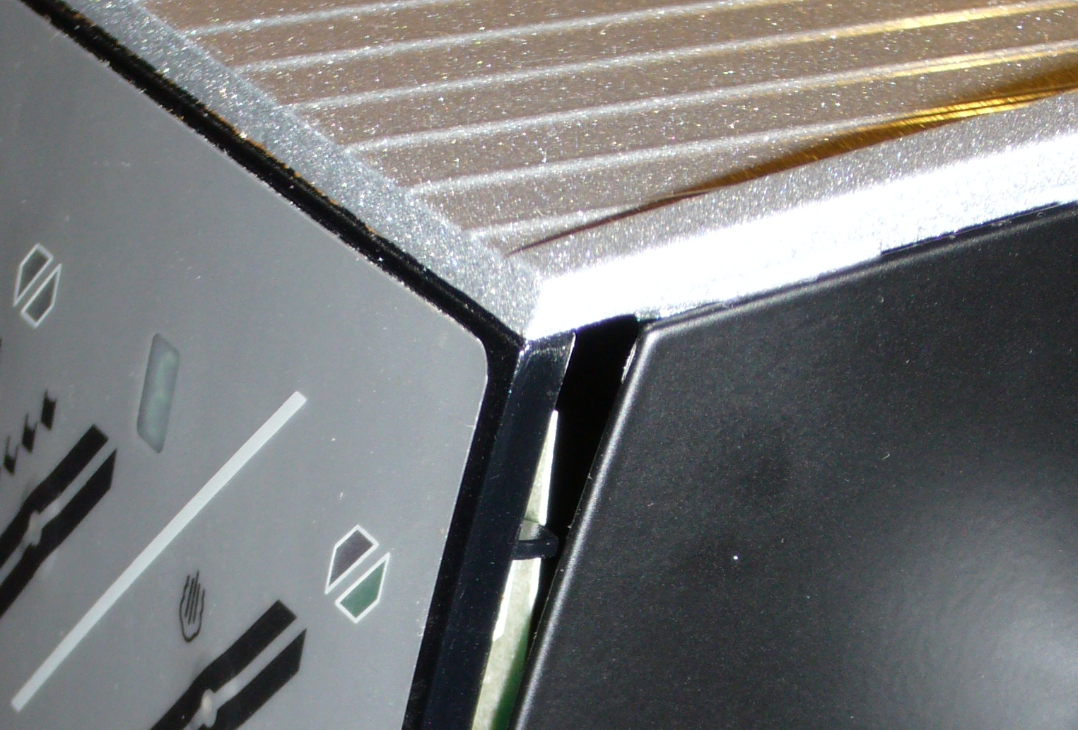
Remove the reservoir. Remove the #1 Phillips screw at the bottom of the reservoir 'lock well' at the back of the cup tray. To remove the cup tray, hold the machine against your chest and gently slide the cup tray forward. Don't go more than 1/2' or you will break off the front panel tabs. Lift the cup tray and lay over the back of the machine on a pile of books. Optionally, disconnect the ground lug and heater connector to completely remove the cup tray.
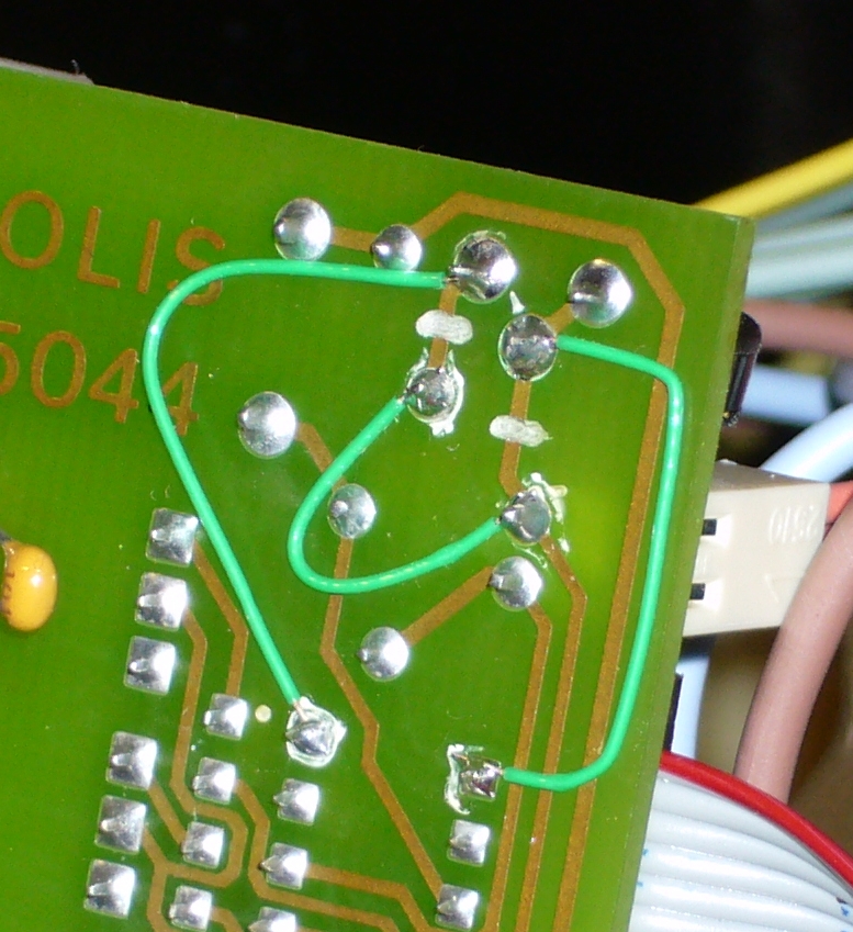
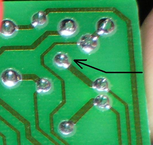
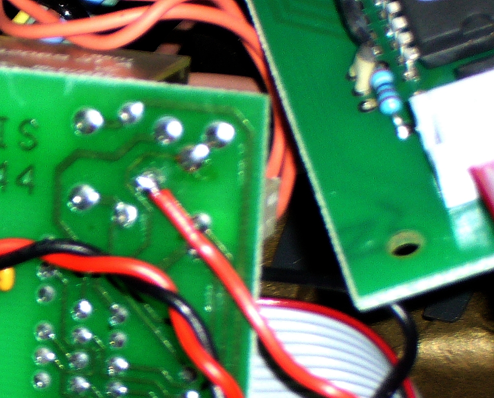
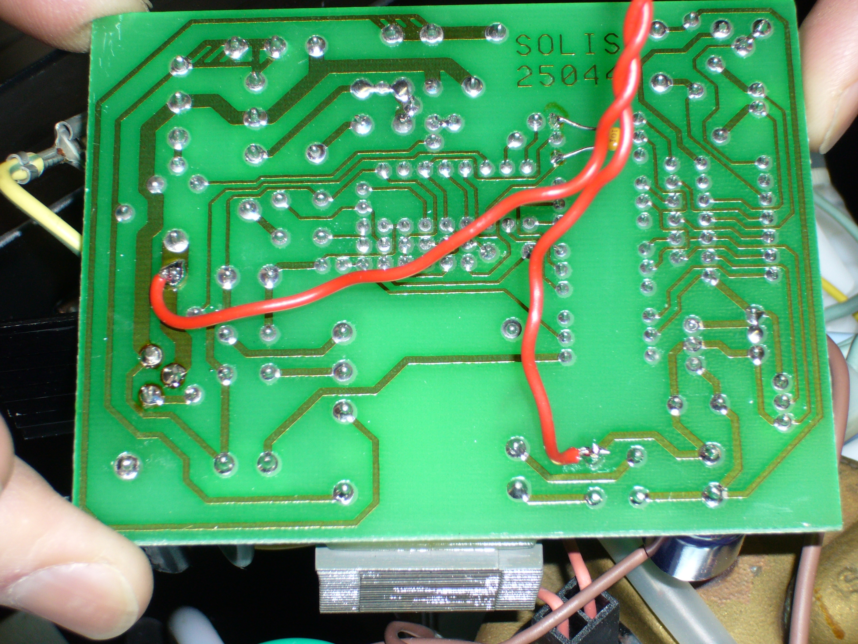
These modifications are not for this PCB. They may work, but have not been tested. Proceed with caution. The PCB number is the same and the modification by the green wires matches the tested PCB. Carefully compare the PCB to this image. If the traces match, proceed. If not, STOP!
15k 1/2w flame proof resistor. (30k: ——[ | | | | ]—— for 220v machines)
T1 LED. Color Optional. The LED is ON when the element is heating.
1N4007 1A 1000V diode. [The 1000V is IMPORTANT!!]
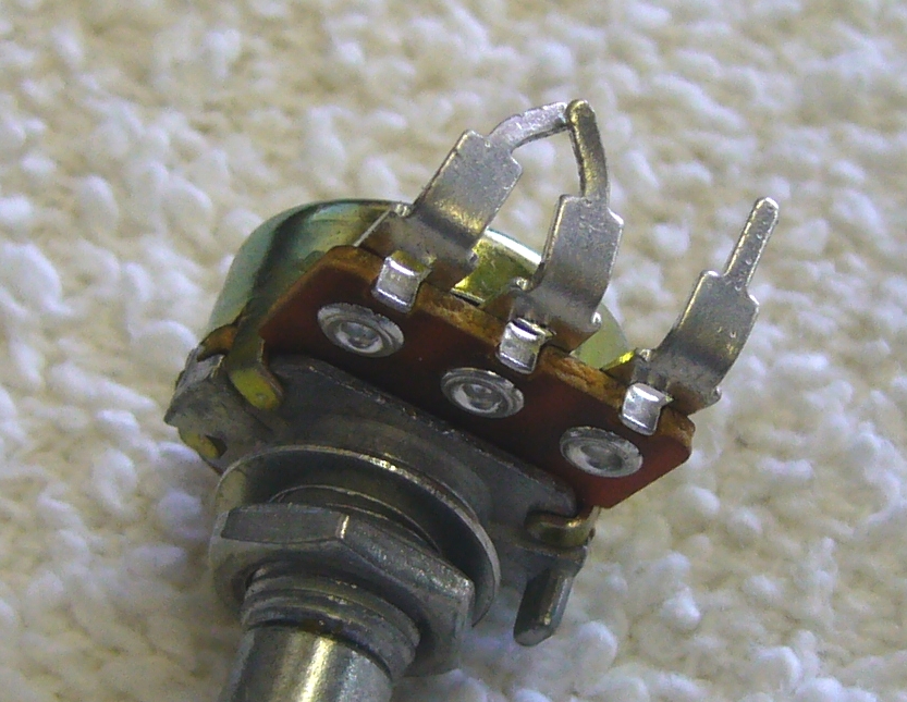
500k LINEAR 1/2in pot and Knob to fit pot shaft
Hookup wire in 2 colors. 105ḞC 20ga is fine.
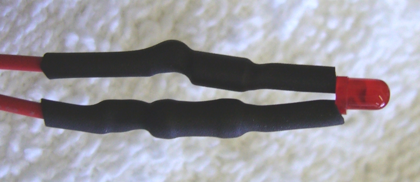
1/8 heat shrink
Solder
Optional: Heat sink compound to replace the dried out compound around the sensor and over temp breaker.
#1 Phillips
Soldering Iron
Wire Cutter / Stripper
Heat Gun
Electric Drill
1/8in drill 1/4 or ?? drill for pot mounting boss. Optionally a rat tail file to enlarge hole from 1/4in
Hacksaw to shorten pot shaft, if necessary.
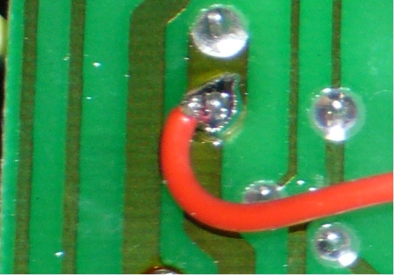
Take care to make good connections and don't take too long as you can destroy the LED and diode with too much heat.
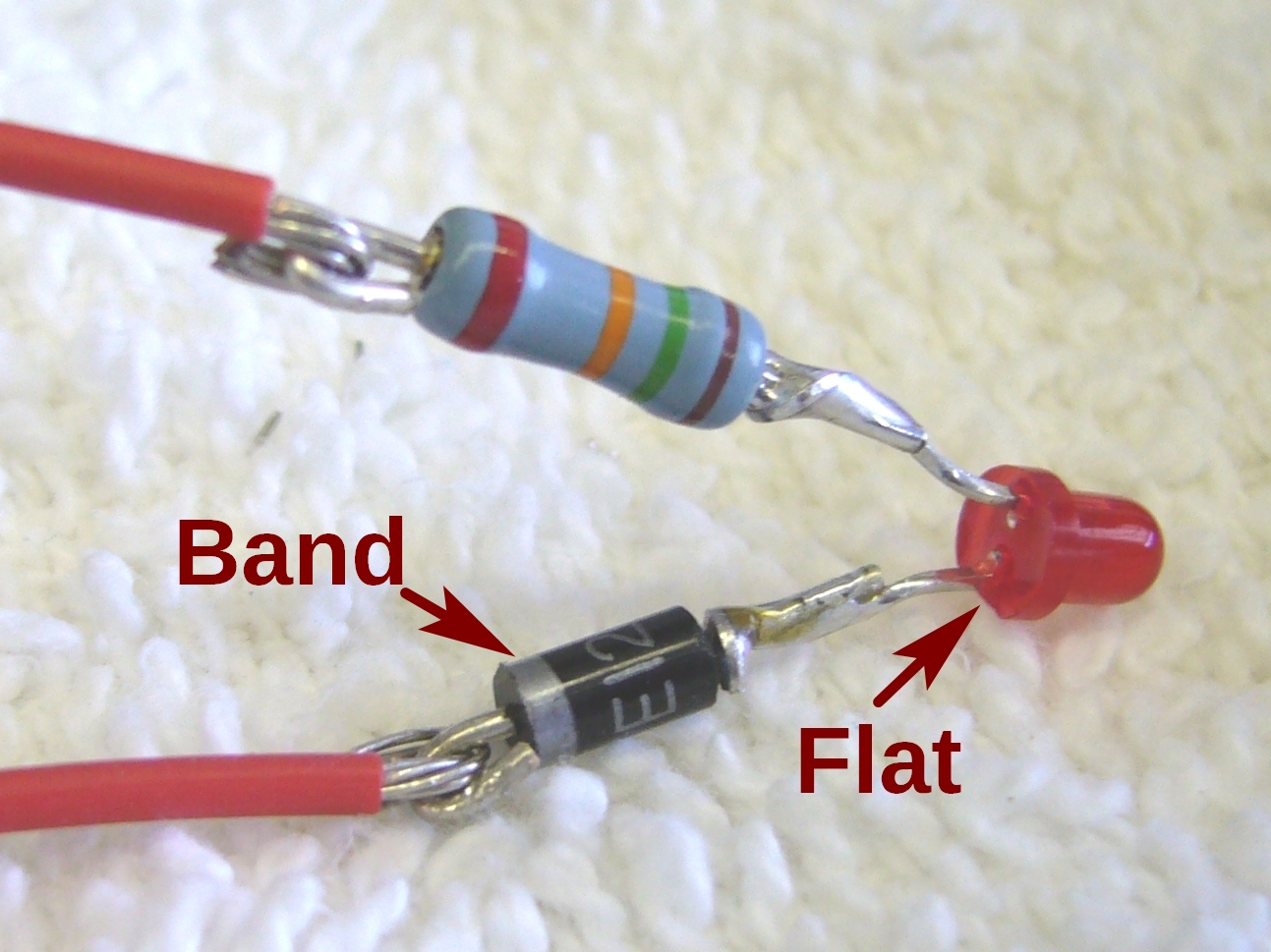
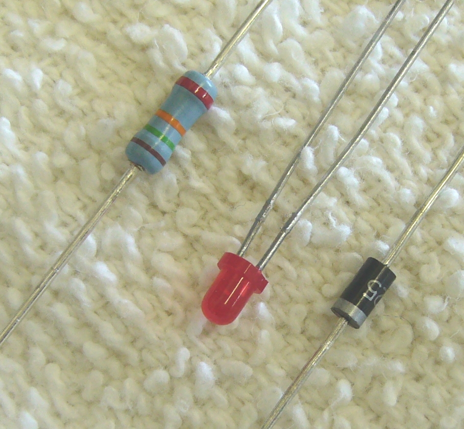
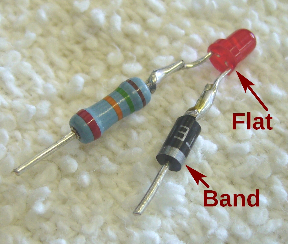
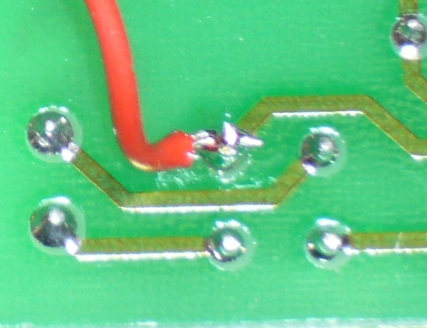
NOTE the FLAT on the LED and BAND on the diode.
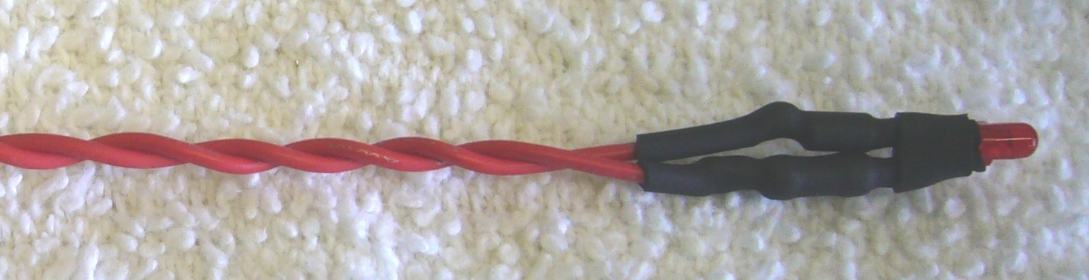
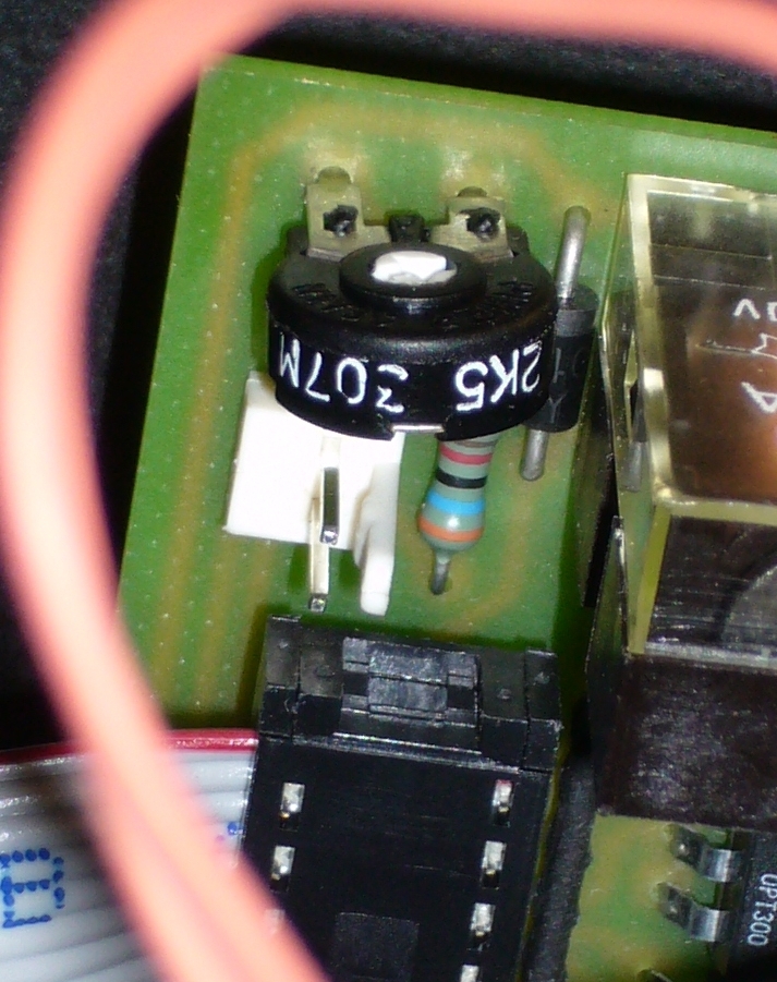
The resistor is the blue thingy in the middle of the photo.
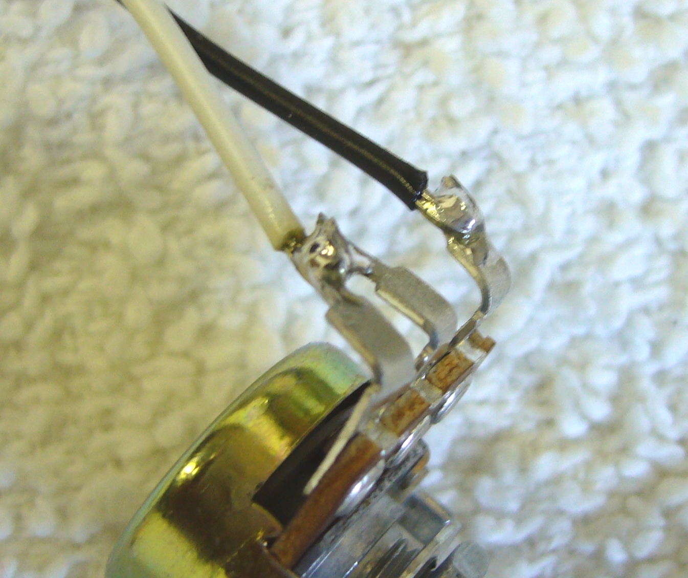
Solder the black lead to the free end of the resistor and insulate with heat shrink.
[The RED lead is the WHITE lead in the photo above.]
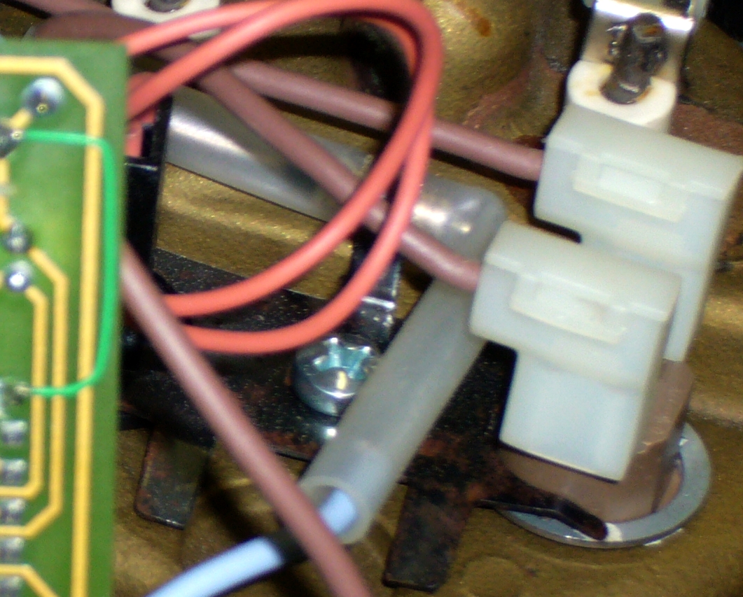
Ensure that you replace the thermal fuse properly under the clamp.