Subterranean Homesick Blues
... please don't phase me in ...
Small SubWoofers
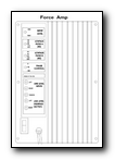
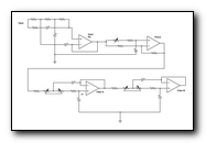
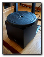
Small subwoofers try to squeeze 10 pounds of performance into a 1 pound box. Thus, they need to 'adjust' the amp response to provide reasonable performance from a driver and volume smaller than could be considered optimum. The Force Sub uses a 250W OEM amp to power a custom 10' driver and claimed remarkably good performance of 20-250Hz ±3db. The Force is no longer manufactured, but its principles apply to small sealed subs.
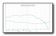
Force measured near field performance. 20-200Hz ±3db which is more in keeping with two 2nd order filters of 232Hz. Top trace is level. Input level for nominal 85db listening position. Registered 120db is due to microphone proximity. Bottom trace is Phase, output inverted, and is remarkably good considering the Input Equalizer phase shift. All in, a well designed product. Sadly, no longer made.
JL Audio makes fine subwoofers. Their article Adding a Home Audio Subwoofer offers helpful information.
The Force Amp
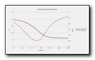
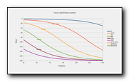
The amp has a large 15db @10hz low end gain starting @ 40Hz to linearize the driver and box. Whenever an equalization is applied, Phase is affected. It's important to remember this when adjusting filters as every filter adjustment may require a phase adjustment as well.
The Force uses an All-Pass filter to adjust phase. Input Eq Gain phase shift negates the phase control markings in absolute terms and they should be used as reference only. All-Pass phase controls operate at only a single frequency with varying degrees of shift across the passband. The horizontal bars on the 22.5° to 135° lines cross at about the frequency at which the marked phase occurs for the All-Pass filter alone. The 0° 90° frequency is 2341Hz and the 180° 90° frequency is 4.67Hz. Note that the phase is not constant across the sub's range. Input Eq Gain phase is added to these values. Filter phase is subsequently added. And finally, the actual driver response. In other words, one might as well adjust the control blindfolded.
The Force uses an All-Pass filter to adjust phase. Input Eq Gain phase shift negates the phase control markings in absolute terms and they should be used as reference only. All-Pass phase controls operate at only a single frequency with varying degrees of shift across the passband. The horizontal bars on the 22.5° to 135° lines cross at about the frequency at which the marked phase occurs for the All-Pass filter alone. The 0° 90° frequency is 2341Hz and the 180° 90° frequency is 4.67Hz. Note that the phase is not constant across the sub's range. Input Eq Gain phase is added to these values. Filter phase is subsequently added. And finally, the actual driver response. In other words, one might as well adjust the control blindfolded.
Any sub with similar analog controls will operate in the same manner. The utility of a 0°/180° phase switch alone is of very limited use as a 40Hz wavelength is about 28 feet and the phase switch is equivalent to moving the sub 14 feet and no where in between! Every other frequency is moved a different distance. A continuous phase control AND a 180° switch offers the best possible solution.
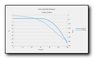
The filter section consists of two 2nd order nominal 35-250Hz filters, 39-232Hz for installed component values. 2nd Order filter phase is about 90° at the corner frequency. Both Level and Phase are cumulative, thus by careful adjustment of the two filters one can approximate a desired level and phase. The graph shows the combined level and phase response of A 130Hz and B 180Hz.
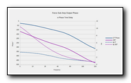
The graph shows the cumulative input, phase and filter for the overall amp response. As can be seen, the phase, and hence time, response @ 180° is much worse than at 0°. The dotted lines show tΦ in milliseconds. Spica's Servo subwoofer used a nominal 18db/oct filter and was inverted polarity. The advantage of this arrangement is, with the Spicas rolled off an additional 6db/oct, the sub can be placed in the same plane as the mains, summing will be in phase and the total phase error will be the minimum possible. At John Bau's suggestion, I added a hardware Phase Invert for an absolute 180° flip to use in concert with the Force phase, low pass filters and passive XO1.
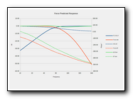
Small loudspeakers are not known for their stellar low end performance. The Spicas have an approximately 2nd order attenuation below 65Hz. Other small speakers will have variation on this theme dependent on the designer's chosen parameters. The combination of the XO1 and Spica response makes for a quite complex filter slope. Integrating the Force, or any 3rd party small sub, is a tedious process. One would do well to ignore the pot legends and simply think of them as More & Less. The graph shows the predicted response of the Force / Spica combo after adjusting the controls by ear. Better than ±1db! Phasor Vector sum is also within ±1db. Not too shabby.
Control values are meaningless for anywhere but this installation and are presented for academic interest only:
Phase: 30° - Filter A: 93Hz - Filter B: 232Hz. XO1: 109Hz. These values are calculated from pot rotations and nominal circuit component values. They will vary due to component values in other hardware. Note that the graph data is calculated from filter and loudspeaker performance curves. Naturally, actual performance will be nowhere near these value due to room, driver and box interactions.
Phase: 30° - Filter A: 93Hz - Filter B: 232Hz. XO1: 109Hz. These values are calculated from pot rotations and nominal circuit component values. They will vary due to component values in other hardware. Note that the graph data is calculated from filter and loudspeaker performance curves. Naturally, actual performance will be nowhere near these value due to room, driver and box interactions.
The Importance of Phase
Some claim that phase is of little consequence. Others counter that minimal phase error contributes to more satisfying reproduction than frequency response. Sadly, a great many HiFi aficionados have never seen the inside of a great concert hall with world class performers. Far too much live music today is needlessly amplified. The microphone, equalization, amplification and reproduction totally destroys any semblance of phase coherence. At a recent performance of a military brass jazz band, there were 25 mics for 20 performers. The result? A gigantic bucket of mush from direct and reinforced sound. The ride cymbal was 'an atonal poinky splat!' Instruments wandered about due to comb filtering of the direct and reproduced sound. Listeners are further conditioned to phase incoherence by Lossy Encoding. See why Lossy Encoding sounds bad. The proof of the pudding is in the eating and when knowledgeable listeners make comments like 'Those little speakers aren't putting out all that gorgeous bass', 'Every other subwoofer I've heard just boomed', 'Joe Pass is sitting right THERE!!' and 'Man, your system is so precise!' indicate that attention to minimum phase error pays very audible dividends.
For an examination of DBA Swarm see DBA Room Simulation
For an examination of DBA Swarm see DBA Room Simulation
Phasors
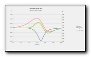
This graph shows the effect phase settings of 0°, 90° and 180°. Sub polarity is inverted. The graphs are vector sums of the amplifier level and phase. Since the level does not change with an All-Pass filter, the level sum is the same for all phase settings. However, when the signal phases are included in the vector sum, the level changes dramatically.
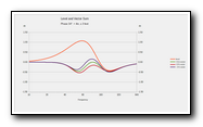
This graph shows the optimum phase setting of 34° and its 4 inch offset from the mains. Additionally, the effect of moving the sub forward and backward 3 feet. Note how very little effect this has, as would be expected with wavelengths of several feet.
In an actual room, boundary effects will modify the response curves, affecting sub and main frequencies to varying degrees based on the sub and main boundary distance deltas.
Sub setup is definitely not plug and play.
In an actual room, boundary effects will modify the response curves, affecting sub and main frequencies to varying degrees based on the sub and main boundary distance deltas.
Sub setup is definitely not plug and play.
Connection
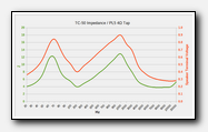
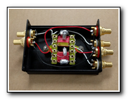
Taking a high level input to a sub from a Tube Amp is a Very Bad Idea.
The speaker impedance controls the LEVEL INPUT TO THE SUB.
The input to the sub is ≈7.7db lower at 20Hz than 60Hz. Blecchh !! Many speakers are many times worse.
SS amps will exhibit considerably less change, but are NOT immune to LS impedance.
Current drives the LS and is not in phase with the voltage driving the sub. The sub introduces its own phase errors which is why ALL subs need Continuous Phase and Polarity controls. Without them, unless the sub was engineered for the system, it’s a crap shoot. Mostly crap!
ROLL THE LOW END FROM THE MAINS AND USE THE SUB LOW LEVEL INPUT !!!
A simple passive XO @ ½ to 1 octave above the main LS anechoic -3db point is a good starting point.
Setup
Before beginning, realize that the ROOM is likely to be the limiting factor!
This Loudspeakers Calculator at Dr J. Hunecke's Room Acoustics is well worth a visit. Sub placement has an enormous contribution to integration and the calculator allows for virtual positioning. Additionally, furniture and room treatments make a large contribution to integration. The calculator allows some limited flexibility in room shape and treatments, but only ported subs. Additionally, the placement tool only works with rectangular rooms. Sadly, WAF often precludes locating and treating optimally.
This Loudspeakers Calculator at Dr J. Hunecke's Room Acoustics is well worth a visit. Sub placement has an enormous contribution to integration and the calculator allows for virtual positioning. Additionally, furniture and room treatments make a large contribution to integration. The calculator allows some limited flexibility in room shape and treatments, but only ported subs. Additionally, the placement tool only works with rectangular rooms. Sadly, WAF often precludes locating and treating optimally.
Integrating a sub 'by the numbers' can be an exercise in futility because the expected control adjustment is compromised by other control interactions. It is possible to get excellent performance if one works slowly with very small adjustments of a single control and knowledge of what is actually happening. An educated ear is every bit as good as the best test equipment. Manufacturers would do well to provide accurately calibrated controls, level and phase information to make integration easier.
Good program material and experiencing acoustic performances in good halls makes set up easier. A good program for getting a subwoofer in the ballpark quickly is a good outdoor recording of a Pipe and Drum band. The bass drum fundamental is low enough to adequately excite the sub. The pipes and drum snares are well out the bass drum region. The music is not overly dense and allow adjustment changes to be heard quickly. Once the mains are properly set up, start by setting 1st filter to the minimum and the 2nd filter, if fit, to the maximum frequencies. Raise the 1st filter until the bass drum is nicely filled. Now adjust the phase slowly until the bass drum snaps into focus. The pipes and snares will also tighten up as the optimum phase is achieved. Iteratively adjust the filter and phase for the most satisfying presentation. If fit, the 2nd filter may offer some additional trimming in the crossover region. Try raising and lowering the 1st filter a little and dialing down the 2nd to see if the integration improves. Remember, any filter adjustment will likely require a concomitant phase adjustment. It's important to adjust in very small increments, a knob rotation of 10° or less. Once in the ballpark, listen to a wide range of material to make final adjustments, preferably over several days, making notes all the while. When the filter and phase are correct, the low end should be detailed and seamless with no impression of a subwoofer at all. On well recorded orchestral music, one should get the impression of the hall stage all the way to the lowest frequencies. If there is too much low end, the stage will collapse between the mains somewhere in the mids. Not enough, and the orchestra floats between the mains without support. On well recorded pop, the foot should be solid and hefty but not at the expense of the snare. Bass should be detailed and localizable. If the foot is too puffy and the snare lacks heft, the corner frequency is too low and / or the phase is incorrect. If the bass is woolly, try adjusting phase. Getting the phase right is as, if not more, important than filter frequency. When the phase is wrong, the low end is a bowl of sonic spaghetti. It's difficult to determine where instrument voices begin and end. When phase is correct, orchestral sections tighten and don't wander as instruments play throughout their ranges. On well recorded pop, multi-miking, double tracking and the multitude of echo and effects devices all become annoyingly obvious.
Finally
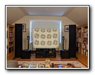
After more than 15 years, we replaced the single Force with two Martin Logan Dynamo 800x. See Double Double for details.
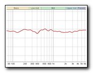
After more than 35 years, we replaced the Spica TC-50 w TriAmped Eminent Technology LFT-8b. Frequency response speaks for itself as to the efficacy of the integration.
After more than 35 years, we replaced the Spica TC-50 w TriAmped Eminent Technology LFT-8b. Frequency response speaks for itself as to the efficacy of the integration.
