
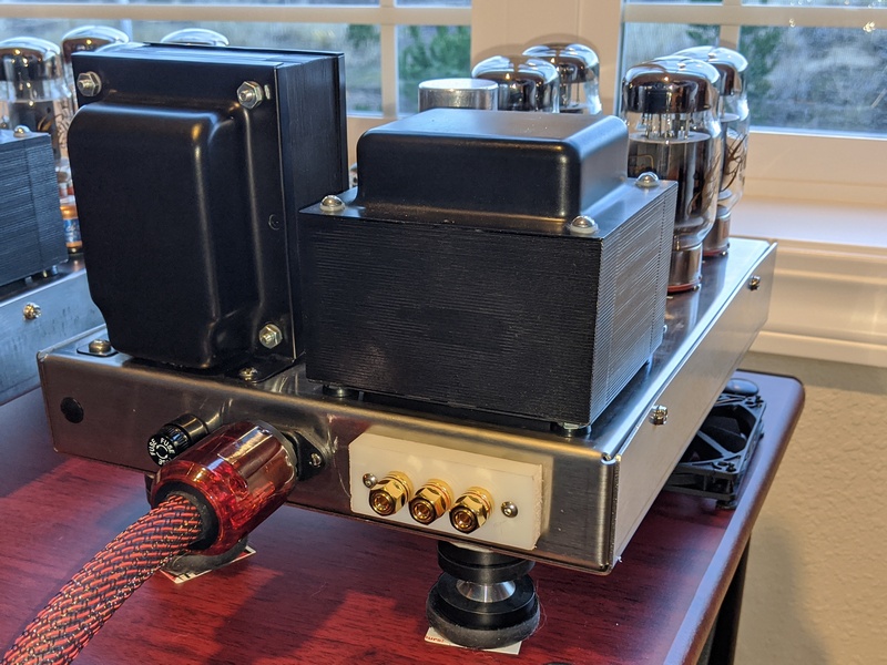
teaching the Tubes4HiFi / VTA M-125 to sing
... humming machinery is fine, amplifiers not so much ...
update 23-March-2025
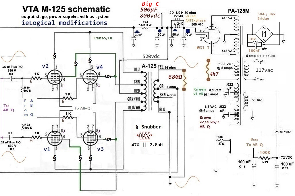
- add M-125 schematic
- add solder station calibration
- update heater wiring instructions for clarity
On Line review comments may no longer apply to stock amps. Transformers may not be the same. CAVEAT EMPTOR!
overview
Power - Detail - Air - EFFORTLESS! The first time I played the 1812 on Chesky CD65, I nearly jumped behind the bookcase when the cannon fired!
Reviewed by Glenn Young and enthused users comment favorably in the Dynaco Tube Forum*, AudioAsylum, diyAudio, etc. The amp is very versatile with both pent/triode modes, and is sonically configurable with a variety of tube combinations. Since my Citation II I've had a soft spot for KT88 amps and owned several. In pentode mode, the M-125 travels a middle ground between the PrimaLuna ProLogue Five [PL5] and NuPrime ST-10**. It's not as recessed as the PL5 nor as forward as the ST-10**. IMO, I'd adjudge the amp a perfect match for the ≈4Ω TC-50s when paired with Kimber BiFocal-XL in my system and ROOM!
March 2020 - Spica TC-50 retired for tri-amped Eminent Tech LFT-8b. NuPrime ST-10** for woofers, M-125s mid and PL5 tweeter. 2x miniDSP 2x4HD for crossover. Kimber Monocle-XL for the mids and HannLinte Braided OFC 10AWG for woofers and tweeters.
** March 2022 - Failing ST-10 replaced with 2x Outlaw M2220 monoblocs. One of the 2x4HD also failed, so both replaced as the originals had 2016 rev boards. See Done & Dusted for ST-10 failures.
October 2022 - miniDSP 2x4HD replaced w miniDSP Flex-8. SPDIF input is slightly more transparent than TosLink from the cd6006. Single volume knob control and level display. Good-bye laptop to keep levels in sync.
As always, YMMV.
Mr. Latino was very responsive to pre-purchase email questions about the amplifiers.
This missive is intended for the competent DIY enthusiast. If you purchased built amps, by all means have at it if you feel competent.
• M-125_ieLogical Schematic
• ieLogical M-125 Ultralinear assy manual to build the VTA / Tubes4Hi M-125 as an Ultralinear only version with improved bias, four power tube bias check... and other assorted improvements. Format follows original build instructions, so you may pick and choose. Please contact ASAP with any anomalies.
• PSU Options to assist build.
• M-125 Debug Workbook to assist troubleshooting.
M-125 SPECs
Power output (4 X KT88)
¿¿¿ Somehow the amps got more powerful with the same transformer specs ???
- Nope. 1kHz 125W distortion is 2.8%. 1kHz distortion reaches 1% @ ≈55W.
Power output (2 X KT88) 70 watts from 17 Hz to 34 kHz at less than 1% THD in ultralinear - 40 watts in triode
- probably not a good idea to run w two power tubes. Could be hard on the heaters.
IMD ........................... < .38% (19 kHz and 20 kHz) at rated power
- Nope. CCIF 19/20kHz d2L is 0.82% @ 6W, IMDpwer is 0.84% @ 0.6W
Frequency response ......... 10 Hz to 35 kHz +/- .1 dB at 1 watt
- Nope. -0.19dB @ 50Hz & -0.1dB @ 11kHz relative to 1kHz
Power bandwidth ............ 17 Hz to 37 kHz +/- .3 dB at 125 watts
- Nope. -0.27dB @ 20Hz & -0.87dB @ 27kHz relative to 1kHz
Sensitivity .................... 1 volt in for 125 watts out
- Nope. ≈1.6v which is somewhat beyond most -10db consumer gear.
Feedback ..................... 10 dB
- Nope. ≈3.9dB
Version ..................... ??? - currently v19 as of 19-Sept-2021
- Nope. PCB layout identical to v15. v16 dropped ground plane fill. At best, these are point revisions, i.e. Circuit layout is the same. Some amps delivered with v16 component values and v19 boards. Mid 2021 schematic has a minor change in component values.
Mid 2021 v19 schematic changes relative to early 2019 v16:
- • bandwidth reduced from 96kHz to 31kHz !?!?!? c12 changed to 680pF
- • a bit more feedback - r8 reduced to 6.8k
- • a bit less gain in the phase splitter - r20/22 changed to 27k
- • a bit lower HP filter to phase splitter - c6/8 changed to 0.33µF
- • it should be noted the above two changes alter circuit voltages, but since these are not accurate, par for the course
- • OP transformer? Above changes could be to compensate for a new transformer, but if so, one should expect sonic deltas. Deltas are not a negative per se, as long as they complement the rest of the system. No component operates in isolation!
Claims for power consumption, SNR, distortion and feedback are grossly inaccurate and likely never verified. Almost certainly not verified for each of the plethora of arbitrary modifications over the years.
We did run a set of measurements. Driver board revision v16. See the Pudding @ lab on the cheap. Load: 8Ω ‖ 16nH
Amps drive Kimber Monocle XL 2.5m & LFT8b mid panel: 10.7Ω ‖ 37nH...
THE AMPS SOUND BLOODY AMAZING !!!
M-125 FAQs
1. Are there any advantages to the 16 gauge stainless chassis?
• Besides the obvious fact that this chassis will never rust, a stainless chassis is non-magnetic and cannot hold a magnetic field.
- Nope. Not all stainless types are non-magnetic. A magnetic field is static and only has effect when interrupted by a conductor. Magnetic permeability determines shielding at low frequencies and stainless is not particularly effective.
• Amps built on stainless steel chassis tend to be quieter than amps built on standard steel chassis.
- Nope. Quieter how and by what properties?
• The 16 gauge chassis weighs about 1.25 pounds more than if it was made of 18 gauge steel.
- So??? It could be made of 12ga black anodized aluminum and likely run cooler. Not that heat is much of an issue with all the hot bits hanging in the breeze.
• The 1.25 pound extra mass better supports the heavy transformers and also acts as a somewhat larger heat sink to help the two transformers run a little cooler.
- Nope. Most of the chassis mass is far from the transformers. Stainless is a poor thermal conductor and the shiny surface is a poorer radiator relative to black anodized aluminum. The output transformer has very little thermal coupling to the chassis. The power transformer has next to none on the vibration isolation washers!
2. How does the VTA M-125 compare in sound quality to your other two kits - the ST-70 and ST-120?
• The M-125 uses the same basic circuit as the ST-70 and ST-120 and sounds very similar to my other amp kits at lower volume levels.
- ??? In what context ??? Components can vary dramatically when placed in divers systems. Pure speculation?
3. What is this 4 output tube or 2 output tube option?
• The circuit is arranged so that the amp may be operated with either two left side and two right side output tubes OR just one left side and one right side output tube.
- A really dumb idea. Mixed up matched sets, repeated tube insertions, repeated bias pot adjustments and running tubes at higher heater voltages will shorten their lives.
ESC or Click Upper Right 'X' to close.
WARNING: Lethal Voltages!!
- Proceed ENTIRELY AT YOUR OWN RISK -
Earth Safety on an AC receptacle is connected to Earth Safety ('ground' in the AC panel).
Direct Connection of 0vA to Earth Safety may give rise to so called 'ground loops'.
We recommend isolating amp circuit 0vA and Earth Safety with a Loop Break, detailed below.

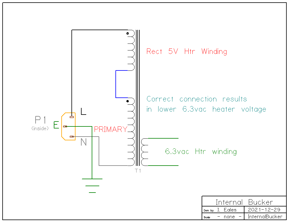
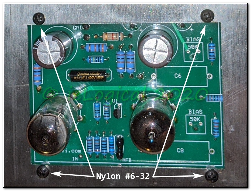
If not using the AB-Q board, an option to make the amps more kid & pet safe is to mount components on the underside of the driver and install a plex cover. This and the unused tube rectifier 5v heater winding bucker mods implemented by WP. Many thanks for sharing, W.
Arrival

In response to a query regarding the 5963 substitution, Mr. Latino replied “In the last 9 years running the M-125s with 5963 driver tubes...” which some might construe Bait and Switch recommending one tube and delivering another.
Additionally, the 12AU7, 12BH7, 5963, 5814, 6189 or CV4003 Plate Characteristics vary considerably. Changing willy-nilly upsets bias, gain structure and distortion.
One option with the 115v transformer and if using SS rectifiers is to use the tube rectifier 5vac filament supply as a bucking winding. This will drop the B+ and heater voltages to more tube friendly values. The winding is rated 25VA, so can handle 5A primary current. Use the same method as the heater polarity test shown in Transformer Polarity Test to achieve lower HV output. BE VERY CAREFUL. Wear insulated gloves and keep one hand in your pocket.
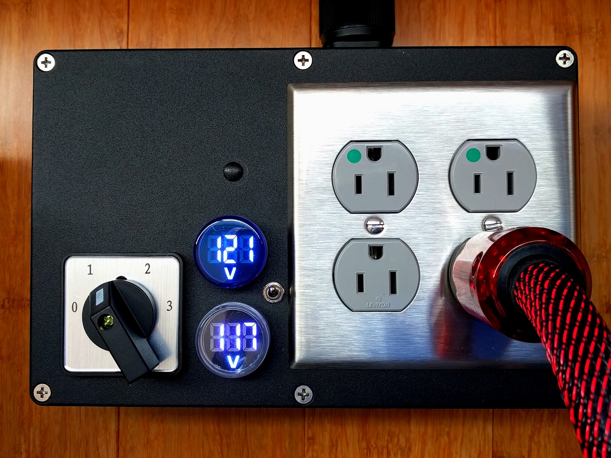
Mid 2020: Amps now ship with <121vac / >121vac primary transformer, obviating the need for a Bucker or VARIAC. If your line voltage fluctates above and below 120, you can wire a 1-0-1 SP or DP switch for a simple mini-Bucker. See M-125 PSU Options
Kit builders estimate about 10 hours to build an amp. There are less than 100 solder connections. An experienced builder making multiple sets with pre-cut lengths should easily complete a pair in about 14 hours. The factory cost to build is $817 or about $50/hr, a not unreasonable rate for an experienced technician, plus about $100 for shipping packaging.
IF ONLY!
CAVEAT EMPTOR
Hummmzzz...
Mr. Latino stated “My impressions are that you are 'over analyzing' the amp and its circuitry when maybe you should just be listening to the music.” Right. On amps with less than 55db SNR!
The 2019 system was minimal: CD6006 -> LC1 -> XO1 -> Amp. LC1 & XO1 are self-designed passives. See Last Hurrah for more details. AC power is dedicated circuit w 10ft run to AC panel. I have multiple amps and ALL are dead quiet. The only Earthed component is/are the power amp[s].
As a bit of background, my company, Studio City Sound Corp, designed and installed recording studio wiring in Los Angeles. With monitor level on S T U N, all one could ever hear is a slight thermal rush. Buzz? Humm? _ N E V E R !! _ Ditto my HiFi for the past ½ century. We designed film scoring panels for studios such as Abbey Road, Hit Factory NY, Sound One NYC, Sony NYC & LA, Paramount, NHK, Skywalker Ranch, Lucas Film, Disney... The Vocal Splicer, distribution amps and other tidbits. I was head of Analog Design @ AMS-Neve, perhaps the world's premier recording console manufacturer, from 1996 to 1998. HiFi grounding is child's play compared to a 96 input analog console, 2x24 track, multiple 2T recorders, hundreds of microphone inputs, outboard channels, tri-amped main monitors, three sets of small monitors, multiple cue systems interfaced across multiple control rooms and studios. I consulted w Monster Cable, Ibanez, Alesis, Yamaha and others wrt the sonic quality of their products. I also designed satellite based system monitors for ocean going freighters, ferries, tugs and large yachts. Bad grounding at sea can be fatal to both personnel and ship.
After several fruitless “It's not the amps” emails, I declined Mr. Latino's offer to return the amps.
surely you're joking, Mr. Latino?
Assembly Faults
Amateurish. Slipshod! Unsafe!! Garbage!!!


I do like a good challenge:
- Left Amplifier Faults
- • AB-Q board linked to driver with short crossed leads making service impossible
- • AB-Q R20-C6 lead across trace on solder mask, wire not in hole
- • fuse lead hanging wire, cold solder joint
- • Earth Safety cold solder joint
- • dry joint on Green Heater CT
- • nicked 6.3VAC power wires separated from AB-Q board leaving stripped end in hole when de-soldered
- • spliced 0vA lead on supplementary cap module
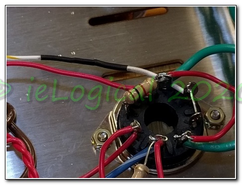
- • AuthentiCap loose, not well secured by tabs and prone to accidental chassis short
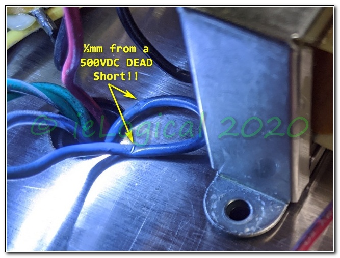
- • output transformer v2/v4 500VDC blue lead pinched between transformer and case
- • dry joint v2/3 fell off when adding snubbers
- Right Amplifier Faults
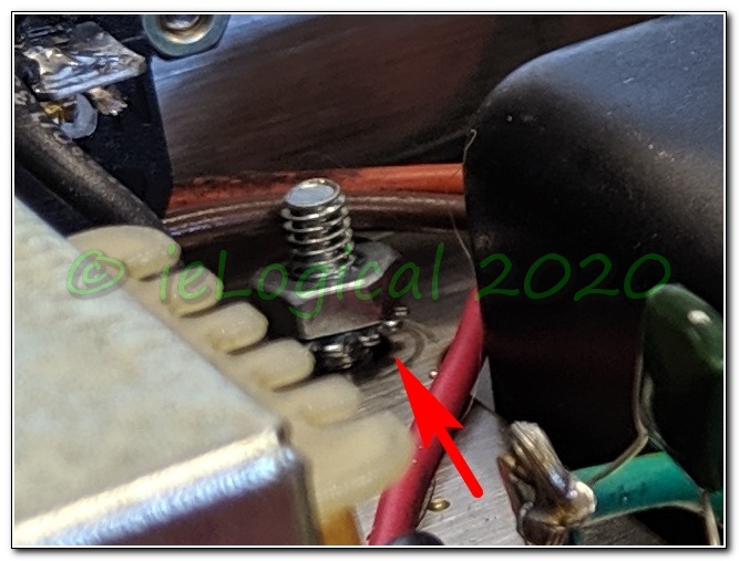
- • power transformer bolts not tightened, barely finger tight, two nuts not down to chassis
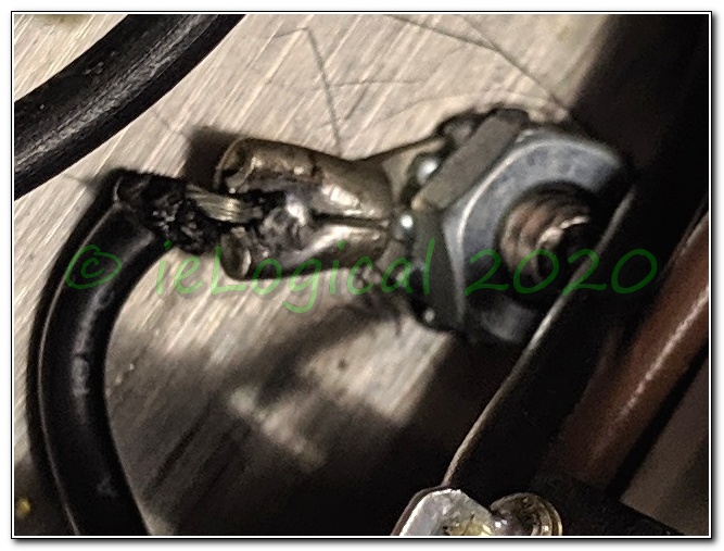
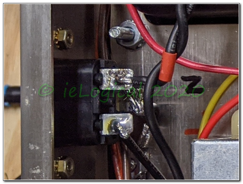
- • VERY POOR Earth Safety ground crimp
- • 0vA 'star' bolt barely snug - multiple 0vA lugs should have soldered jumper
- • fuse Holder not tight, about ⅓ turn loose
- • ESL cap solder to fwd 0vA lug, leaving long uninsulated lead exposed which could touch 0vA on AuthentiCap
- • AB-Q 6.3vac 0vA lead nicked and broke when de-soldered to fix polarity
- • v2 bias lead nicked, broke on AB-Q removal
- • dry joint on NFB lead which showed up after about 150 hours
- • dry joint on r14 robbing v6 of current
- • R22-C8 lead to ABQ board fell off
- Both Amplifier Faults
- • AuthentiCap 0vA cold joint
- • dull grey solder joints indicative of low-temperature/dirty iron and/or movement during cool
- • insufficiently flowed solder 'tacks'
- • inconsistent assembly: some leads wrapped around terminals, some pass through, some just tack soldered
- • inconsistent wire lengths, twist, connections and solder joints
- • bias measurement jacks not snugged - required ½ turn to tighten
- • speaker binding posts insufficiently tight. Rotated when finger tightened. Required ¼ to ½ turn to tighten.
- • spliced AB-Q leads
- • inconsistent and wrong heater wiring for use in two tube ½ power mode
- • melted insulation
- • overly long wire strips leaving uninsulated 500VDC B+ unnecessarily exposed
- • uncleaned driver board flux blobs
- • speaker Black nuts stripped, plastic rotates and will not tighten on spade
- • teflon insulated wire for AB-Q. Teflon is very difficult to strip w/o special stripping tool.
That several leads broke indicates incompetence/wrong tool - • 20k & 30k resistors swapped starving v6 and applying 300vdc to v7 rated 250v MAX
Mr. Latino did not respond to email reporting assembly faults.
Design Faults
- • Power Tube Schematic REVERSES C6 & C8
- • Multi-point 0vA:
- ⏚ AuthentiCap
- ⏚ soldertab 1
- ⏚ soldertab 2
- ⏚ Earth Safety ground
- ⏚ driver board mount
- ⏚ driver board 0vA loop
- • Nichicon PT series driver capacitor voltage ratings are too low.
Rated 400VDC. Max applied voltage is 510VDC w/o tubes and 455VDC w tubes on 115VAC line. Higher on 120VAC. Replaced w Rubycon 100µF 500V 10-12k Hrs @ 105°C.
Either a valve rectifier or B+ delay MUST be used. Rubli HTR214 Rev D highly recommended. ≈27s delay and no contacts to degrade, unlike Tubes4HiFi / VTA TDR offering. The Tubes4Hi / VTA TDR board holds off the 415VAC to the rectifier. As this winding is unloaded until the relay closes, the voltage will be considerably higher. Without current limiting, the 8A/250VAC relay contacts are going to take a beating. The TDR is not recommended with the AudioAmp AB-Q boards. - • v7 LM334 CCS lacks temperature compensation.
Location causes L/R imbalance due to temperature drift. LMM334 case temperature oscillates 45-55°C over several minutes, concomitantly changing phase splitter current flow and thus, gain.
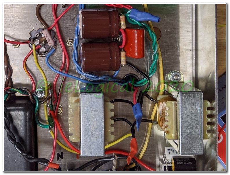
- • choke wiring poorly routed and fields reinforce
- • DC wiring is cheap PVC. Solid 20ga 600v 150°C Silicone preferred. 300v OK in a pinch. Can be VERY difficult to find.
- • AC BIAS wiring run next to DC
- • unterminated tube rectifier heater winding
- • 120VAC power wiring adjacent to audio DC
- • long audio input lead run through choke field
- • long feedback lead run through choke field
- • feedback and input leads run parallel
- • mismatched power transformer polarity
- • ESL capacitor location
- • v1&3 tubes should be mirrored and HT leads run between pairs for best CMRR
- • speaker jack binding post mount inadequate for heavy cables, jacks rotate
- • power tube sockets should use flat head screws or be atop the chassis to preclude KT&88 rocking
- • non-standard 16mm speaker terminals spacing - three crammed into space for two - precluding better quality WBT or similar
- • Mode Switch contact rating is overkill for required current. Under rated for applied voltage. Performance may degrade from non-use.
- • feedback taken from 16Ω tap, compromising 8Ω & 4Ω distortion
- • marginal 75µF SCM w 8x ESR of Big C modification
- • marginal sub-chassis ventilation
- • stability components omitted
- • no output transformer "no load" protection
- • two heater circuits with unbalanced loads compromising 60Hz noise
how bad can it be?

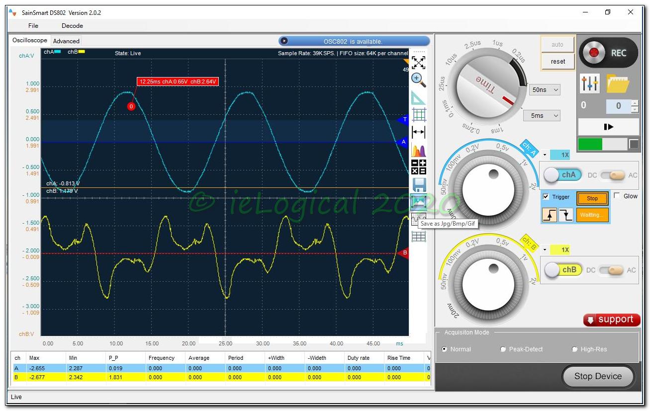
“I had someone test the M-125s about 9 years ago. He came up with a -95 dB signal to noise ratio. I do not know how that was 'weighted'. Typically with good input driver tubes, you have to put your ears on the grille cloth to hear any hum/noise with speakers of average efficiency.”
Either amp alone was somewhat quieter. Not quite ear on the grille cloth quiet, but better.
With amps connected to source, hum/noise almost tolerable at seating position 4m distant.
Jigs
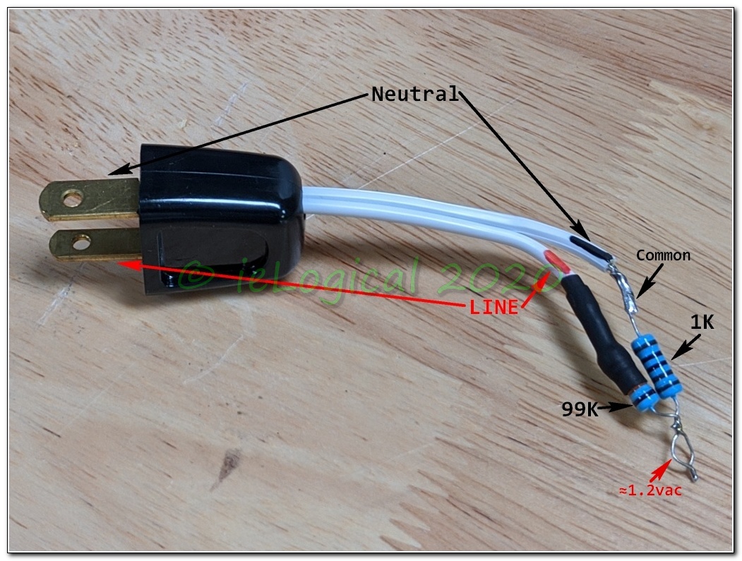
This adapter should only be used for initial transformer polarity determination. See Transformer Polarity Test for an alternate method of determining heater polarities. Once polarities are determined, one of the heater voltages referenced to 0vA can be used for reference.
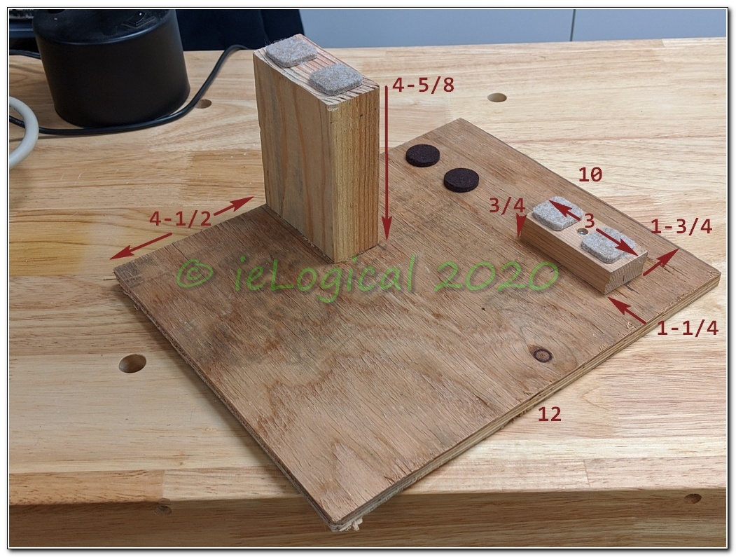
Build Stand: A pair of stands make working much easier. Heights are ex-pads. [From similar on The Dynaco Tube Audio Forum]
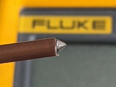
Meter Probe Tip Protection: Insulate all but the very end of the +ve probe. This will help prevent letting the smoke out. All electronics run on smoke and when you let it out, stuff stops working.
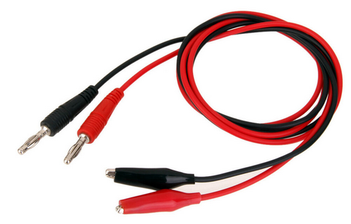
Clip Leads: Useful as a second pair of hands. When probing High Voltages, use a clip lead for the 0vA reference, keep one hand in your pocket and probe with the insulated tip. The life you save is your own!

Solder Iron Calibration

It appears that ≈660°F / 350°C is the new SN63 gospel, but I’ve used 700°F / 371°C for 50+ years on many tens of thousands of connections as it gives bright clean joints quickly. The bright joints make it easier to spot a poor one.
Keep the tip clean, apply solder to iron to wet the tip, apply tip to the work and feed solder to the work, not the tip.
Hakko sells the FG-100B for ≈$300 USD. Chinese knockoffs of the older FG-100 are available on Amazon and eBay. A similar item JF-191 recently became available. While I'm not a fan of Chinese knockoffs, in this case the extra $200 is a bit much for such a simple device.
A quick and dirty test on an adjustable iron is to set it, if possible, to the solder melt temperature. At that temperature the solder should just barely melt. If it doesn't cal is low and if it melts instantly, it's high.
Test mid-point cal by holding a 1/4 inch flat blade screwdriver in the steam from a boiling kettle for a couple of minutes. It should read very close to boiling point at your altitude. See Boiling Point at Altitude Calculator as boiling point decreases 0.5°F with every 250 feet of altitude.
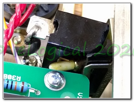
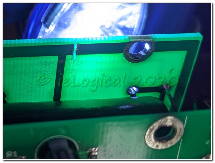
Correct PCB Solder Flow


When we build PTH boards, all component leads are bent so as to ensure they remain securely in place and the leads clipped prior to soldering! The joint is not stressed post soldering making for more robust assemblies.
In the image at left, there is no flow in the PTH. The resistors are discolored and the board is blackened from overheating, probably due to fractured PTH. In the right image there are two faults in the NFB. Not a huge stability issue on the M-125 as there is minimal feedback, but may cause level jumps and ugly sound due to non-linearity in the fault.
If the solder only connects on one side, the PTH can eventually fracture from temperature cycling causing increased heating, noise and eventual total failure. Before that happens, there can be hard to diagnose intermittent issues: Snap! Crackle! POP! Oscillation! A tube amp OPT protects the speakers from a DC failure, but it can still get pricy when a set of power tubes bite the dust.
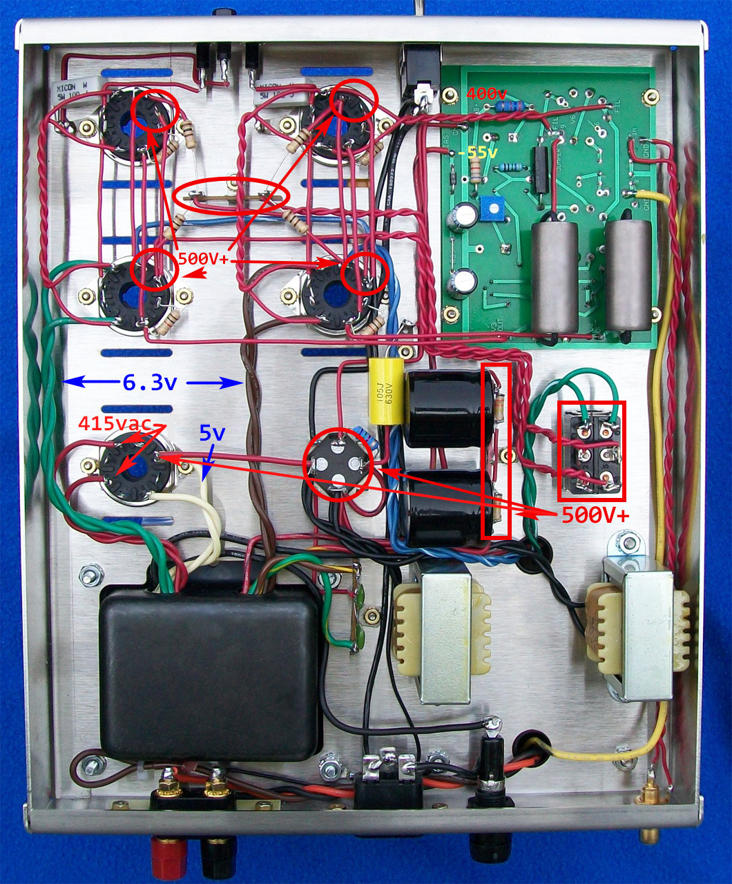
Power Transformer Polarity
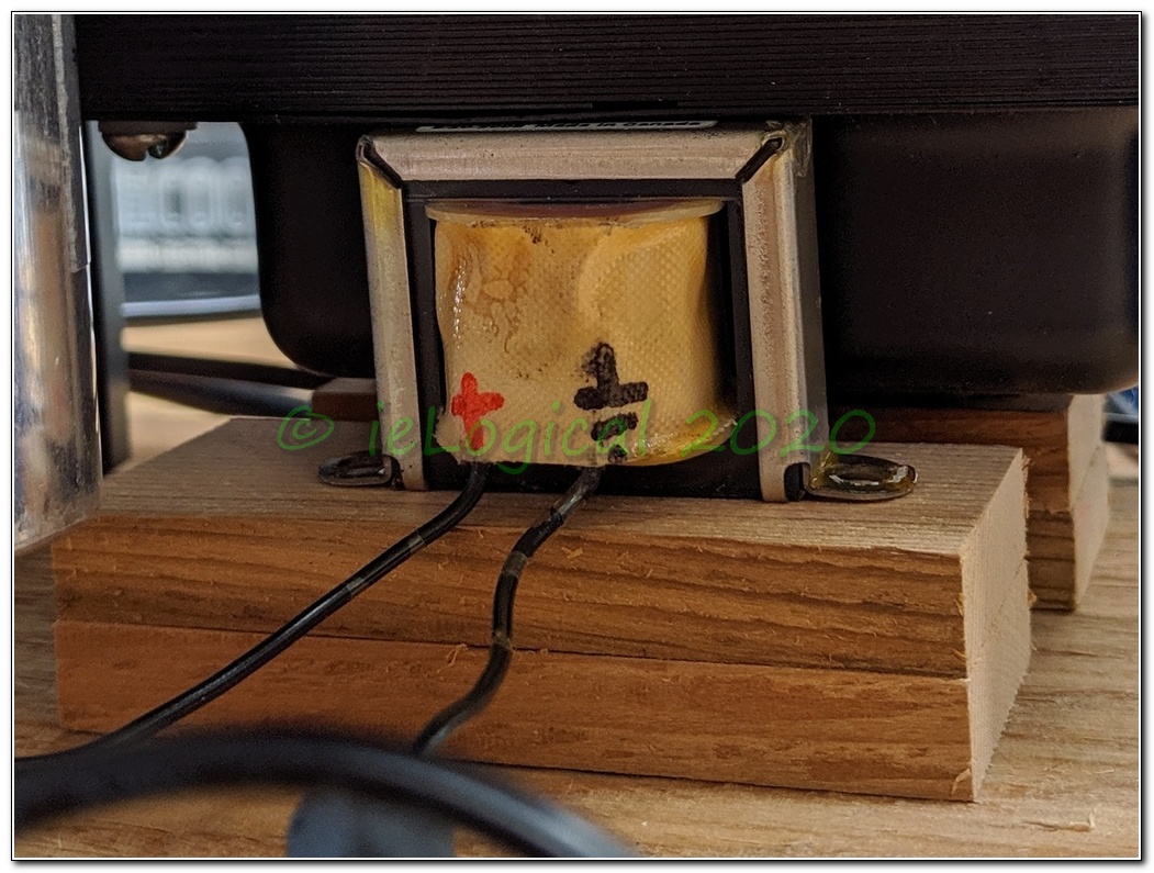

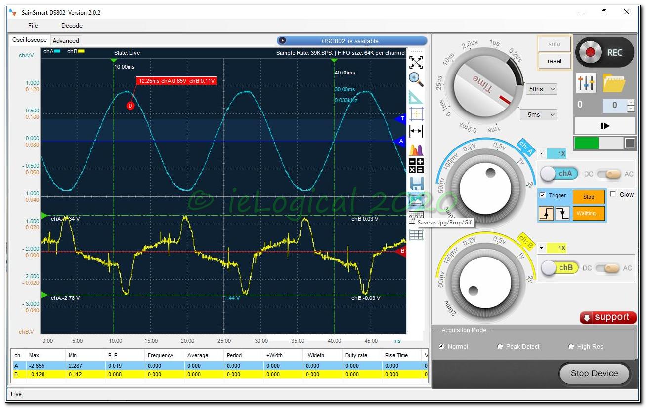
Polarity can be detected by means of a choke placed next to the power transformer and the choke output measured with a scope synced to the line frequency. Choke lead polarity is arbitrary, but marking it keeps measurements consistent. Measure only one amp powered at a time. As can be seen, the power transformers were inverted relative to one another. Choose the less noisy polarity and mark the power transformer leads, fixing as necessary.
Input polarity matching is easily performed before the power transformers are inserted in the chassis. A variac will allow using a low input voltage considerably reducing the output voltages and consequently, the danger.
NOTE: This is predicated on the transformers being wired identically.
The BIAS winding is internally connected to 0vA allowing its use as a reference for matching transformer polarities.
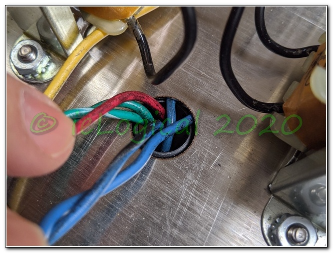
• Insulate all output leads on the two power transformers except 0vA [RED-YELLOW] and —BIAS [RED-BLACK]
• Connect the secondary 0vA leads together.
• Connect the primary transformers in parallel and apply a low voltage. Measure the —BIAS voltage to 0vA on each transformer. It should be about ½ the applied input voltage.
• Measure AC voltage between the two —BIAS leads.
If the voltage is near zero, the transformer primaries are in phase. If it is near the applied input voltage, the transformers are out of phase. Swap primary polarity on one transformer and retest.
Subsequent to my amp delivery, VTA entered the mid-20th century supplying amps with a < 120 and a >120 to <123 VAC power transformer taps. That should ensure correct polarities, but it never hurts to check. I recently used a small 250VCT transformer, Hammond no less, with secondaries wired in phase. In other words, 0VAC between the taps. Neither I nor Hammond had ever seen similar and all Hammond transformers are 100% tested. Hammond replaced it gratis.

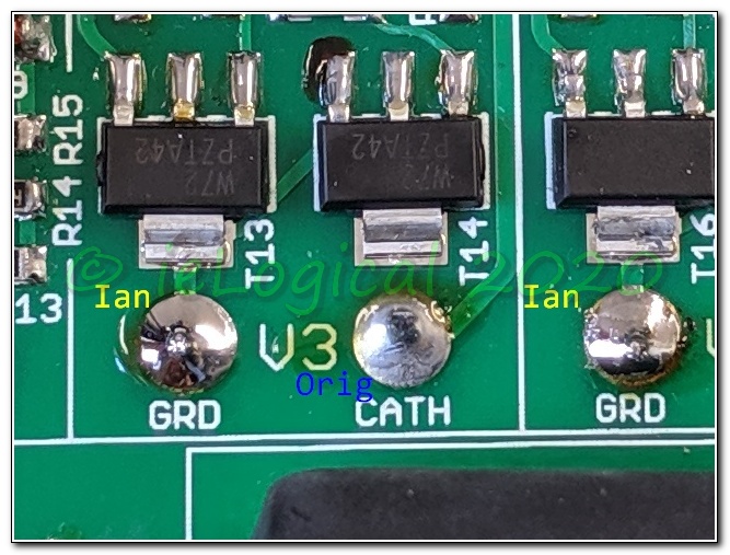
The lower block shows the effect of a correct Single Point 0vA. As built, with the nine point 0vA there is resistance between each gain block. 0vA currents shift the reference. With a true single point 0vA, the relative voltage at each gain stage does not shift.
Heater Wiring
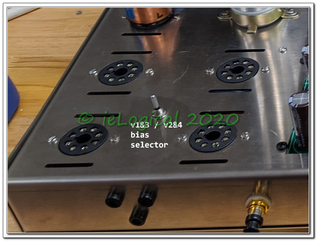
A feature mentioned on the website: “NOTE - The amp may also be operated with just TWO OUTPUT TUBES - one of v1/v3 output tube and one of v2/v4 output tube.” NOT recommended as it requires re-biasing and increases heater voltages. Constant bias pot twiddling dramatically shortens their life.
Given that there is no provision for determining output heater polarities, arbitrary polarities on any tube pair could compromise SNR. If half power operation is planned, ensure heater polarities are the same for socket pairs v1/2 and v3/4.
PRIOR TO CONNECTION, secondary polarity can be determined by wiring the transformer in a series configuration. See Transformer Polarity Test. USE CAUTION AND MAKE NO LIVE CONNECTIONS!!!

NOTE: For pairs of tubes, e.g. four output tubes, heater polarity should be inverted between the tubes. Tubes in mechanically the same location, e.g. v1/v2 on the M-125 should have the same heater polarity.
Heater Over Voltage
See Emission Labs TB-05 'Heater Voltage vs Tube Life'
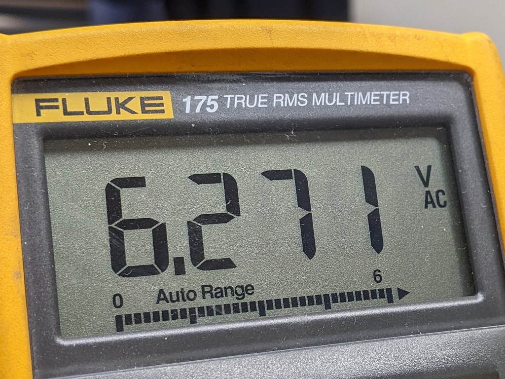
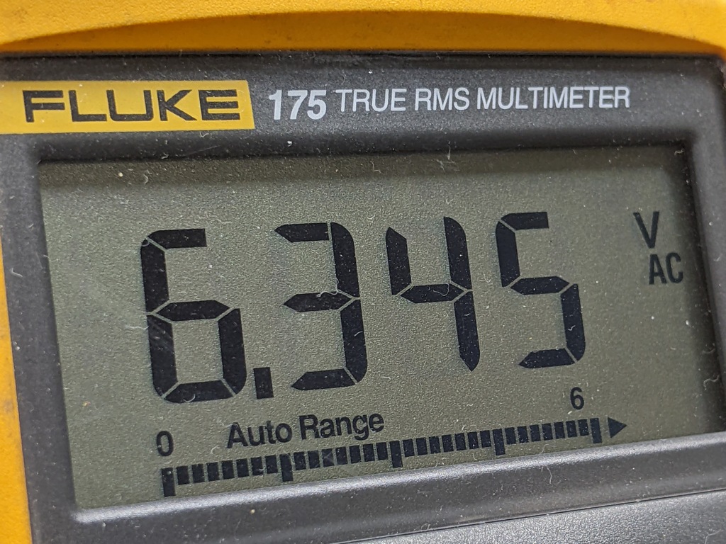
In the M-125 running at the correct power transformer voltage, heater voltages are about 105% for v1&3 and 107% for v2&4. Adding 0.05Ω in each leg of the heater supply drops this to very near ideal 6.3VAC.
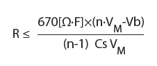
Adjust resistor value as necessary for local voltages. Formula to calculate: = ((Vin / Itot) – R||) / 2. Vin is nominal 6.3, Itot is total current of all tubes on the supply and R|| is the effective resistance of the parallel heaters @ 6.3 volts divided by the current. Note that datasheet current values are often approximate and individual tubes vary by manufacturer and age. Using datasheet values, the difference in the calculated dropping resistor value is less than 0.002Ω for both 6.3vac supplies versus R calculated from measured 6.3/I. For precise results use a regulated power supply and measure the currents for the tubes in use at 6.3v. Parallel resistances are calculated thus: Rt = 1 / (1/R1 + 1/R2 + 1/R3 + ... + 1/Rn) for all the tubes on the supply. If there are four tubes, there must be four 1/R terms.
To make things easier, their is a Heater V Drop sheet in the VTA M-125 Debug Workbook to assist calculating dropping resistors for up to a dozen tubes in parallel.
Heater Polarity Chart

Polarity is best determined before the transformer heater wiring is connected.
The right amp v2/v4 heaters were in-phase when they should be out, contributing to the as built 4db SNR reduction.
It was determined by inspection that Modified polarities produce the most benign noise signature in the M-125s I received. Other Revisions might require other choices.
With so many revisions in so little time, it's Amp of the Month Club!
DC Wiring

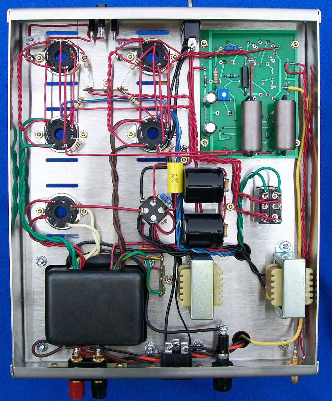
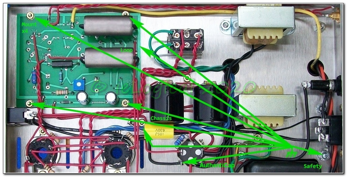
Chokes are not counter-placed to cancel fields. Chokes sit directly BELOW the Output transformer. Minimizing field radiation pays off.
 terminal to the rear choke leads. Wire the choke output direct to the AuthentiCap. Link the AuthentiCap to the Supplementary Cap Module [SCM]. Connect the output transformer RED lead to the SCM. Wire the linked AuthentiCap
  &
&  terminals and the added black lead to the SCM input. Wire the ESL film cap across the input and output of the SCM.
Miscellaneous Wiring
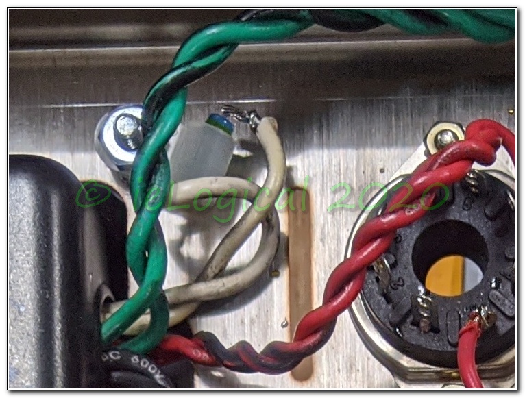
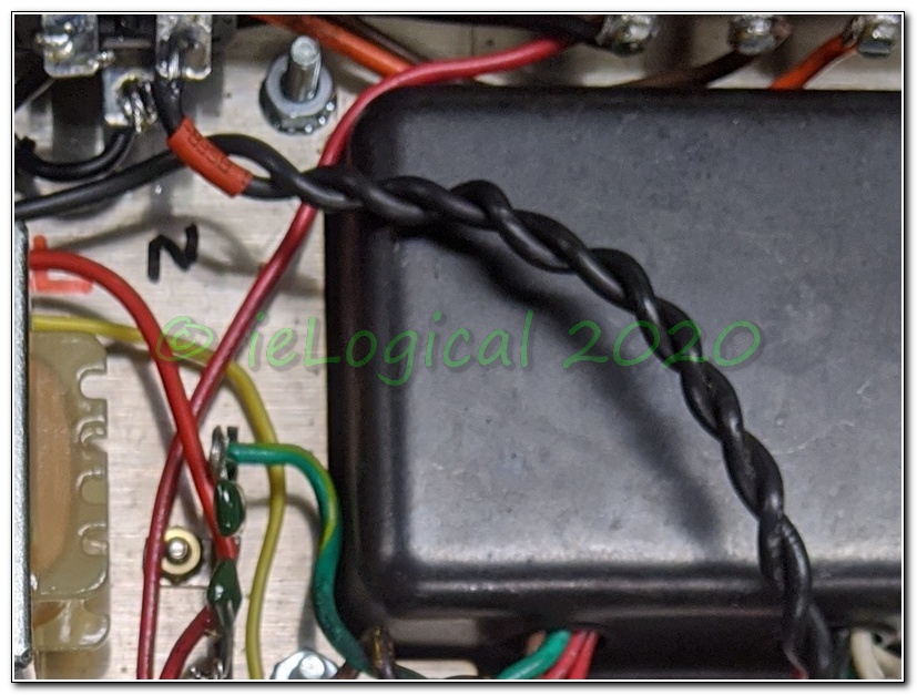

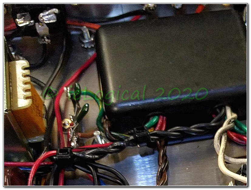
AC Input: With externally controlled systems, a power switch is superfluous. It's never a good idea to run 120VAC leads in close proximity to DC or signal wiring. Hard wire power transformer to IEC socket and route away from all other wiring. If a power switch is required, mount it on the rear panel. This will cut hum substantially.
If your must have a front mounted power switch, twist its wires over as much of their length as possible.
Audio Input: Without the power switch, there a convenient hole on the front panel for the Audio Input jack. In addition to short leads, the audio input no longer passes through the choke fields and maximizes distance from the AC power fields.
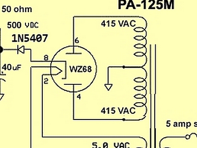
Tube Rectifier: Great for MI, not so much for HiFi. B+ sags under high current reducing dynamics and increasing distortion. If you must, you can protect the power transformer from catastrophic tube rectifier failure whereby the capacitor bank discharges through the primary, possibly destroying it. Simply add a 1N5407 3A/800PIV diode between the capacitors and the rectifier. See Yellow Sheet Improved sketch above. Some claim you need two diodes between the transformer outputs and the rectifier input to prevent a transformer short when a gas plasma develops inside the rectifier. If there is a gas plasma inside a vacuum tube rectifier it is toast! The single diode on the rectifier output protects the transformer B+ winding, the 5vac heater winding, the capacitor bank and blows the line fuse.
GroundLifts/CheaterPlugs are DANGEROUS, Irresponsible and in some locales, ILLEGAL!!
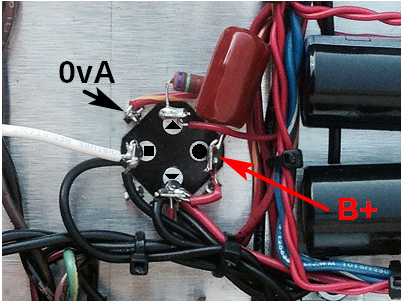
Single Point Ground
Rod Elliott has a very good page on Earthing and Ground Loops in particular. The bottom line is that there should be only one 0vA point. FULL STOP! The Earthed chassis should function as a Faraday cage only and ne'er the twain shall meet.
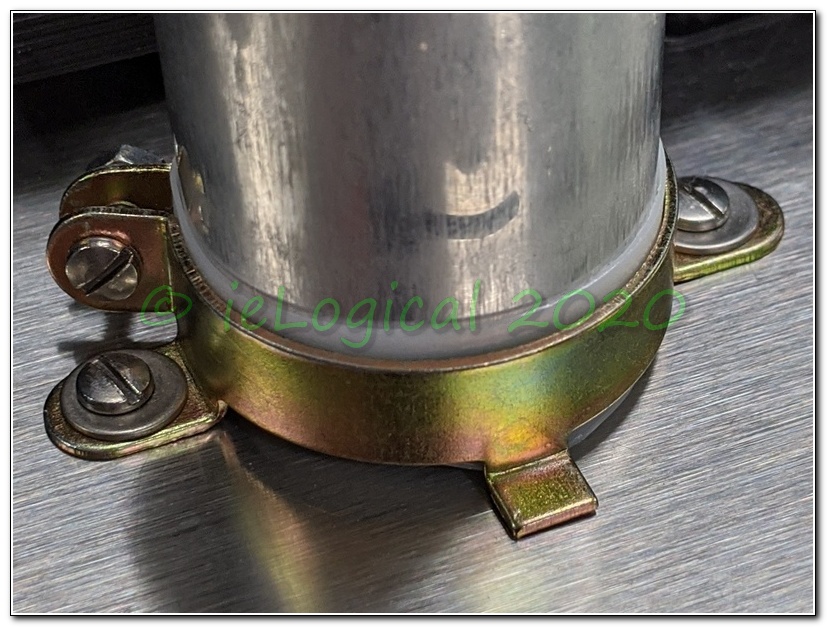
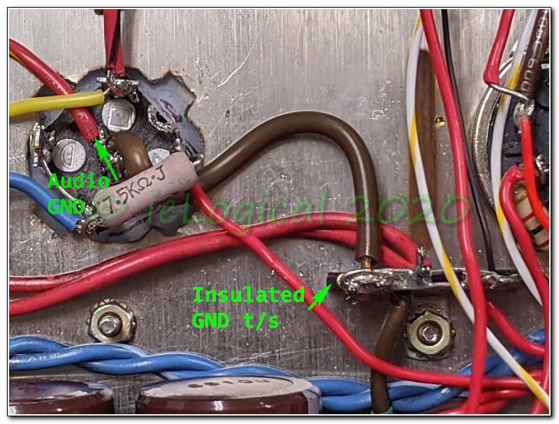
Add clearance for 0vA tabs. Insulate it from the chassis. Mount it securely with a clamp! Bend the ground lugs inward and add a shorting link across two, connected to the 0vA Star terminal strip. Wire transformer 0vA to this link.
GND Star Point: Replace the ground lugs with an insulated terminal strip similar to the one used for the triode mode resistors. Add a buss through the lugs. Link to the AuthentiCap 0vA and solder all ground leads here.
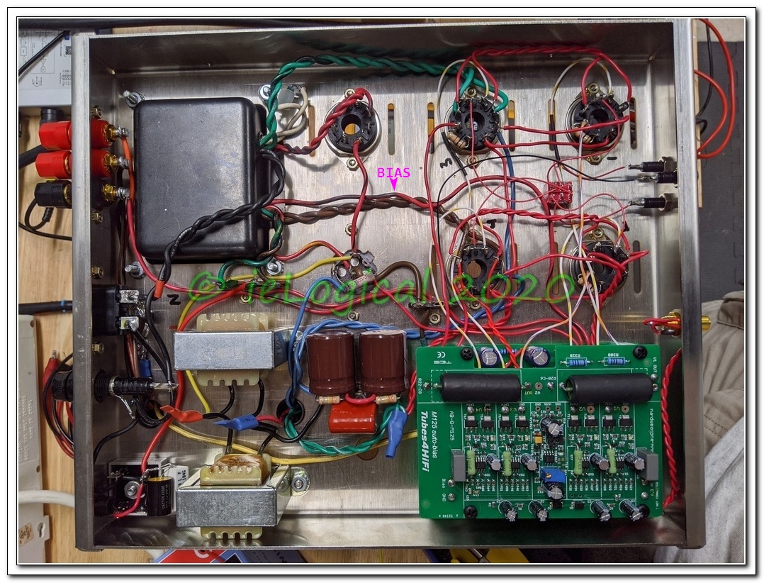
BIAS Wiring: Remove BIAS lead from wire loom and run down middle of power tubes. The pulsed ½ wave rectified DC has no business loomed with Audio DC.
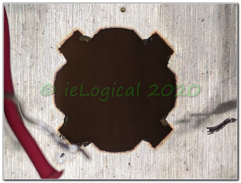
McMaster-Carr #6 for isolated 0vA:
• #6-32 x 3/4 Hex SO 92319A658 • #6-32 x 3/8 Pan Head 94735A729
• #6-32 x 5/8 Pan Head 94735A732 • #6-32 x 1/4 Hex SO 92319A610
Other versions likely have a similar fault, but the cut point may be different.
making it safe

Amazon: 2x 50A diode bridge Parts Express: 10R resistor • 100nF capacitor.
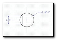
Space is tight, so it is necessary to enlarge the right-rear output transformer chassis hole slightly to 11/64 in. [4.5mm]. A #8 x 1 in. bolt is required. Link 0vA at the heater ground buss. Tie the Earth Safety link at the same bolt as the AC input Earth Safety.
things are looking up

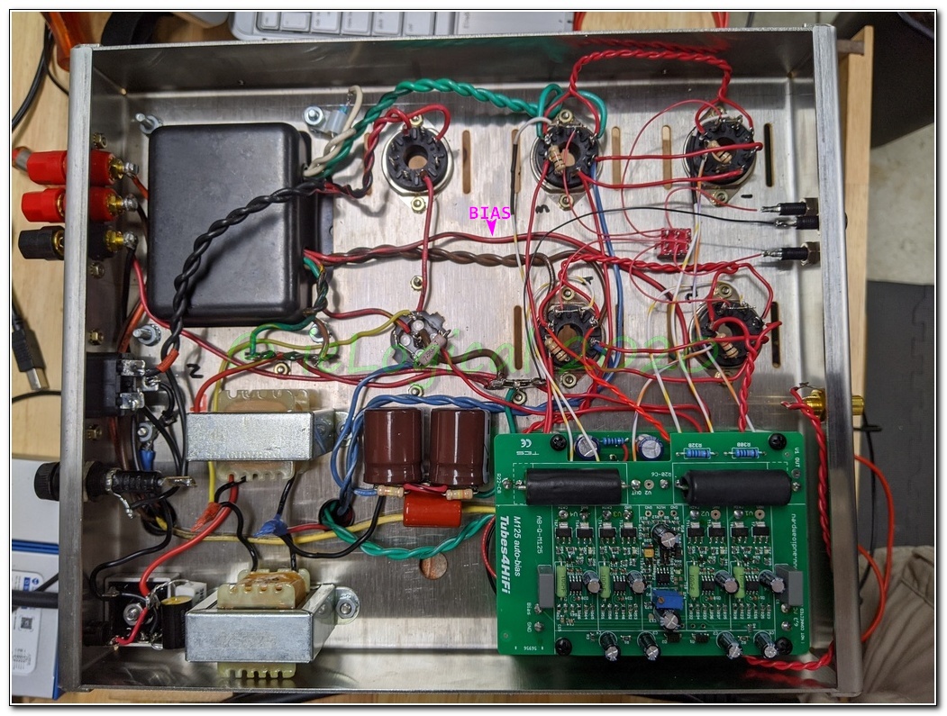
be careful, your bias is showing
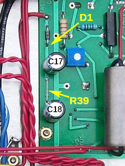
Note that some schematics have incorrect C17 & C18 RefDes.
R39, shown here as a link, should be 1kΩ to improve noise performance.
The 50k single turn pots are better replaced with Bournes 339P 50k allowing for much easier manual bias adjustment. Only adjust bias after the amp has idled for about 30 minutes.
The correct AB-Q connection point is the C18 end of R39.
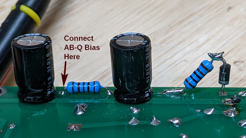


Holger @ Erhard Audio, the U.S.A. agent of the AB-Q AutoBias in 2019, was kind enough to tell me that replacing R39 w 100Ω and moving the bias lead to the C18/R39 junction would allow enough current for the AB-Q board and add a little LP filtering. C17 & C18 were reversed on the schematic in 2019 relative to the PCB.
Current AutoBias boards come with an isolation transformer for the 6.3vac power which isolates the AB board power from the amplifier tube heater supply.
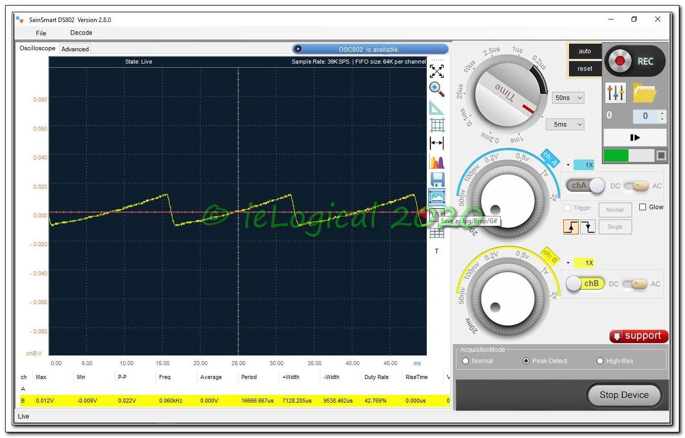
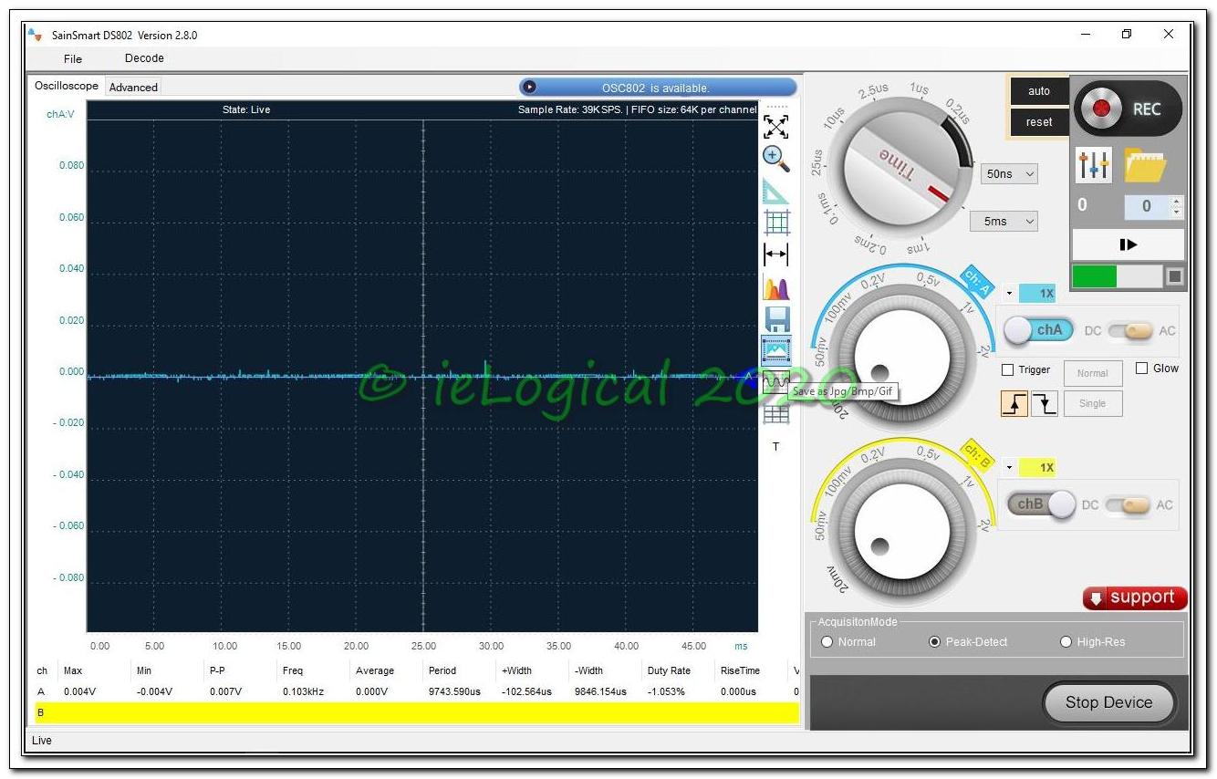
Right image LP filtered bias is 13db better - but not as good as a full-wave regulated DC supply.
Maybe later... arrived. ALMOST. See Regulated Bias below.
AutoBias is EXCELLENT! All tubes hold idle @ -0.500v -0.001v/+0.000 and do not drift. With steady state signal applied, they hold precisely. A much better AutoBias implementation than on the PL5. AutoBias was not measured as built, only on the corrected build.
why AutoBias?
- + Set once and forget. Typical small cermet bias pots have a limited number of adjustments and frequent adjustments can wear them out resulting in bias drift or worse: runaway
- + Multi-turn pot for precise bias voltage
- + Bias remains stable regardless of amp temperature
- + Bias remains constant as tubes age
- + Audioamp boards have a hold off to allow the heater to get hot limiting anode startup current if the amp doesn't have a soft-start
- + Heaven for those silly enough to 'roll' tubes. See Tube Rolling Mythology
- — Some think autobias limits dynamic range
- — Matched sets can differ in their Gm curves despite what it says on the box and Gm will continually change over the life of the tube. In a quad if there are two stronger tubes on one phase and two weaker tubes on the other, distortion increases unless the amplifier has an AC balance adjustment.
- —AutoBias only sets the idle current.It will not save itself, the OPT or the tube if the tube suffers a catastrophic failure.
- —On the non-transformer power input boards, 0vA and one side of the heater are connected, thus grounding one heater winding. Whether this contributed to the issues blamed on the AutoBias board that are likely caused by poor 0vA initial design and/or poor assembly is unknown.
These are my 9th tube amplifiers, 2x M-125 counting as one. The last two are AutoBias and, perhaps due to my advancing age, I might not buy an amplifier without it! [See back 2 BASIC below]
The new AutoBias boards have updates to make them more bulletproof to get around some of the Tubes4HiFi flaws. Also available are isolation transformers to DC isolate older AutoBias boards from the heater supply.
ieLogical has no affiliation with AudioAmp.eu or Miller Audio.
it doesn't get any better than this

ok, maybe a little better
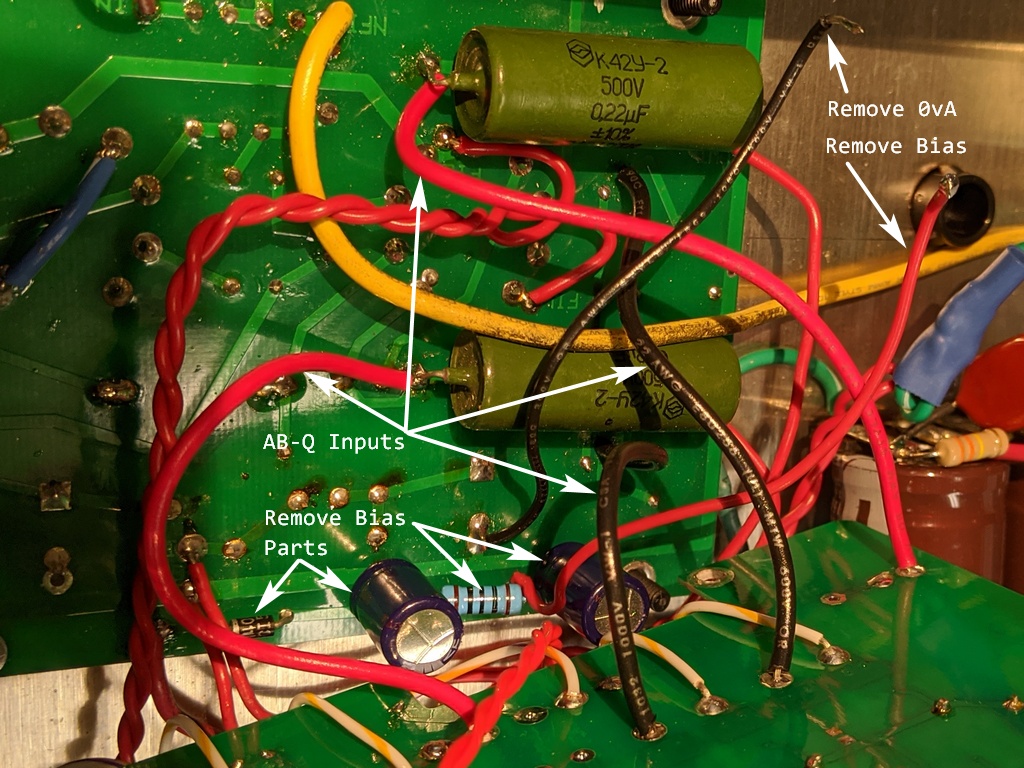

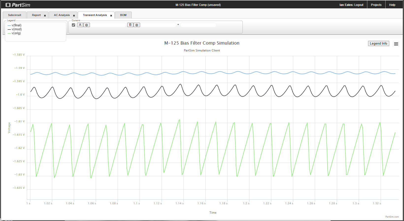

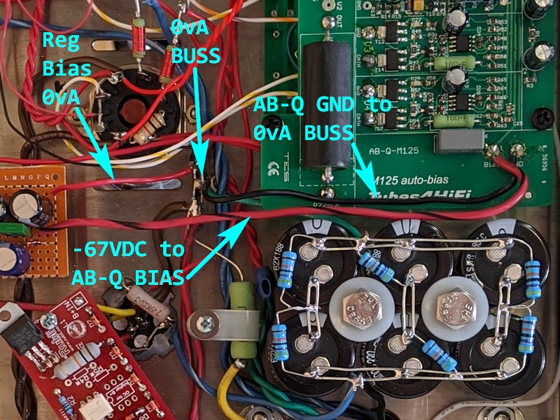
Power tube current is returned to the AB-Q board. AB-Q 0vA should be returned to 0vA star. First image is recommended AB-Q connection, wires and parts to remove. Second image is bias supply to AB-Q board.
AB-Q current requirement is very low, ≈11mA. 3rd image compares simulation Bias noise of factory, first 100Ω mod and the filter in the 4th image. A 26db improvement over factory! -55VAC can supply at least 55mA.
regulated bias


This regulated bias circuit could be used to replace of D1, C17 & C18 on the driver board. -67v would connect to the -ve end of C18 and VR1 & VR2
Unweighted SNR is now >100db wrt full power.
ieLogical Revision
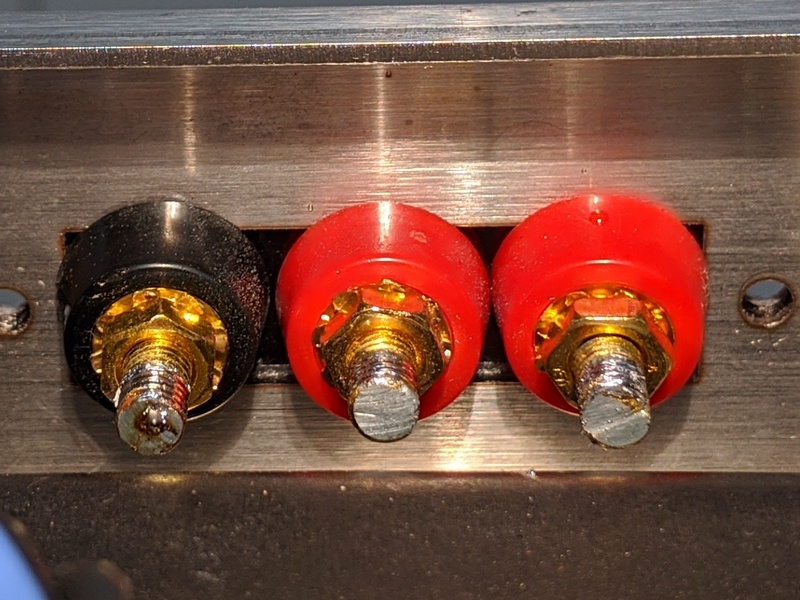
Binding Posts

Replaced with Vampire BP-HEX from Parts Connexion, now obsolete as Sound Connections shut their doors. Parts Connexion doesn't have anything suitable except for silly money. Their own offerings have set screw for wire termination which is to be avoided as will no make a gas tight connections and is subject to loosening with repeated thermal cycles. I suppose the screw could be discarded and wire soldered through the hole. The connectors are quite massive necessitating a very powerful 100w iron to get a good joint.
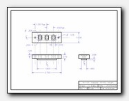
Mount is milled nylon, but can be 3D printed.
M-125 Mount STL & M-125 Mount SLDPRT courtesy of JD.
'Audio Zealots'† will understand that the background is now inky black. Delicate sounds shimmer, decay goes longer, impact is more stunning.
Very Nice Amps, Bob & Roy. Truly!
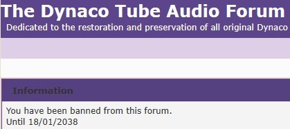
banned!
'teaching the VTA M-125 to sing'
3 lines:
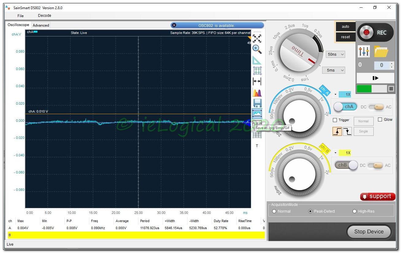
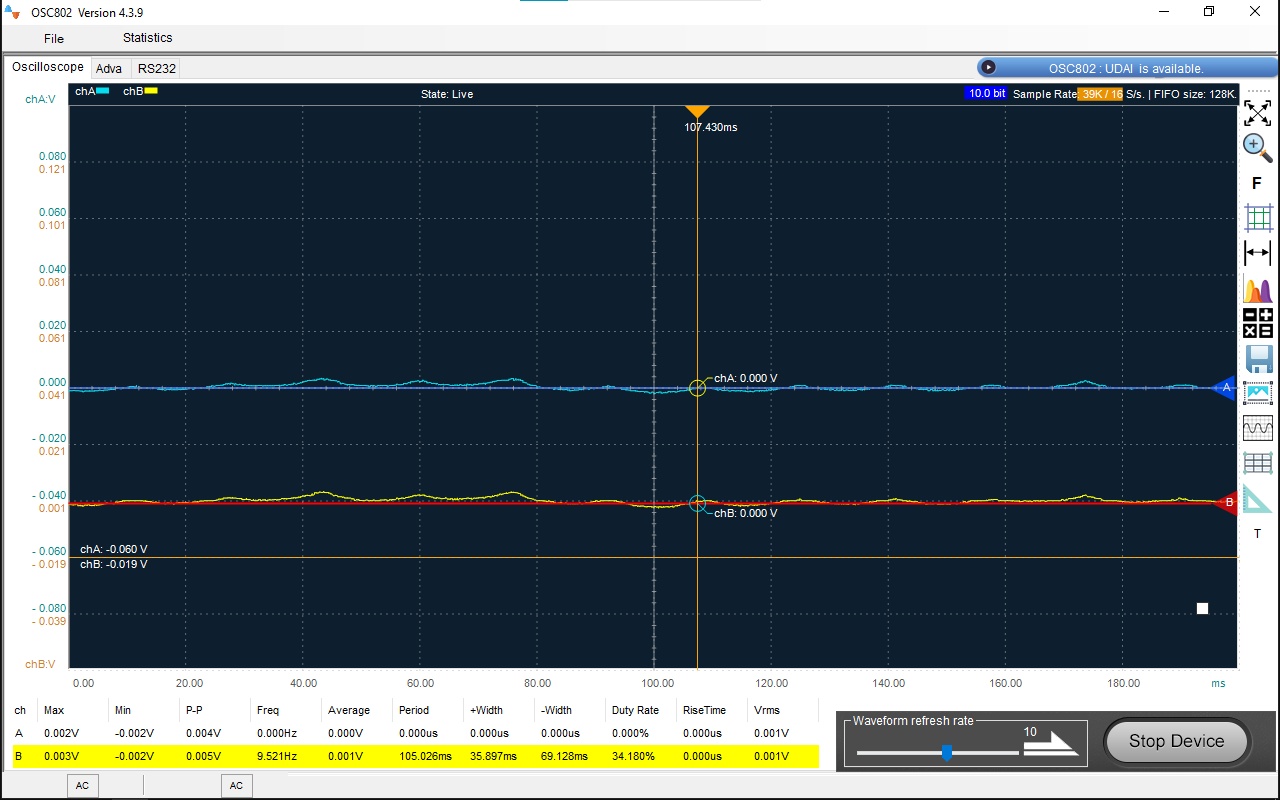
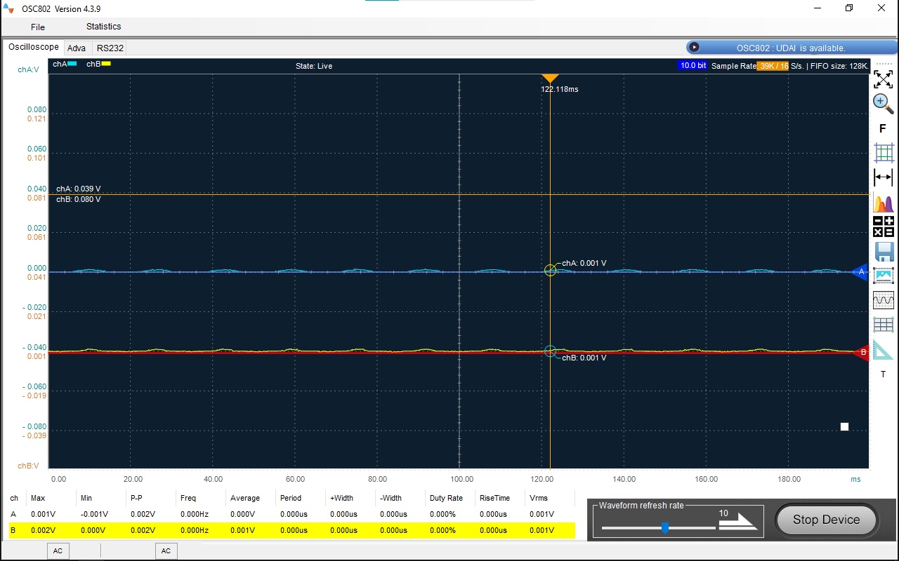
- my VTA built M-125 amps were noisy
- it is possible to make them almost 40db quieter
- a link to this page
4 images showing the noise as delivered and as quietened
* - One has to wonder about DTAF comment validity when accounts are banned for anything critical and unrelated topics deleted. Subsequent to posting this page, many Tubes4HiFi product owners have written confirming a lack of transparency and support from Messrs. Latino and Mottram.
† - Mr. Latino referred to me as an Audio Zealot because I didn't like a PoS Chinese Variac he recommended. In reply, I detailed numerous faults by whom I consider competent, not fan-boy 'it lights up' Amazon users. Posts deleted.
who ARE those guys?
“The sonics of the amp will be the same with the AutoBias board. You won't really hear any difference in sound quality with the AutoBias board installed. I personally have never compared the two (manual bias and AutoBias) MYSELF but others tell me that the sound is the same. The AutoBias board will give you greater convenience.”
All AutoBias products and references scrubbed from Tubes4Hifi.
Mr. Latino states on diyAudio in VTA M-125 mono block kit. on diyAudio:

In response to a pre-purchase query about the AutoBias boards, Mr. Latino stated:
“The cost for just me buying the two autobias boards for the two M-125s are $180. To install them would be $100 for the two boards ($50 per each amp) - Total > An extra $280 for the cost of the two boards + installation. The cost is high. It takes time after installation of the board to adjust the boards for the proper bias”
Yeah, right. All of 30 seconds per amp to adjust level in a shop with a 6.3vac supply.
In response to to a query about R39 specific to AB-Q, Mr. Latino stated:
“I can tell you that on the M-125s R39 can be either a 1K resistor or a jumper wire. I use a 1K resistor but a jumper wire will work OK also. What R39 does is that it sets the 'range' over which the bias may be adjusted.”
Mr. Latino exhibits complete ignorance on something as simple as a voltage divider and LPF relative to the AB-Q install. VTA's instructions are at fault as proven by the 15db noise reduction when the AB-Q is properly installed. See be careful, your bias is showing above.
Why the complete turnabout from the six pages extolling AB-Q products on DTAF AutoBias board on Roy's website?
I'm beginning to think Tubes4HiFi / VTA may be good at copying 1950s designs when 117VAC did not have a Earth Safety connection, but incapable of designs for US Standard Earth Safety Grounded [since 1959] 120VAC [since 1967]. Their designs may work in some, but not, all systems. They may be completely out of their depth in solving issues from bad instructions and design. “Easy? Help — Hard? Ignore”
Mr. Latino stated in the above referenced diyAudio thread:
“I am now not recommending the addition of the autobias boards to any of the VTA amp kits or wired amps.”
Based on experience to date, a Tubes4HiFi / VTA non-recommendation may be a ringing endorsement.
Adding Insult to Injury: DTAF users are not informed that an account is banned. User messages to banned users cannot be replied on DTAF. Users may think the banned user is giving them the shine.
Messrs. Latino & Mottram: Truth will out!
<Soto voce: Should these guys decide to go into politics, their integrity is well on its way.>
the project that wouldn't die
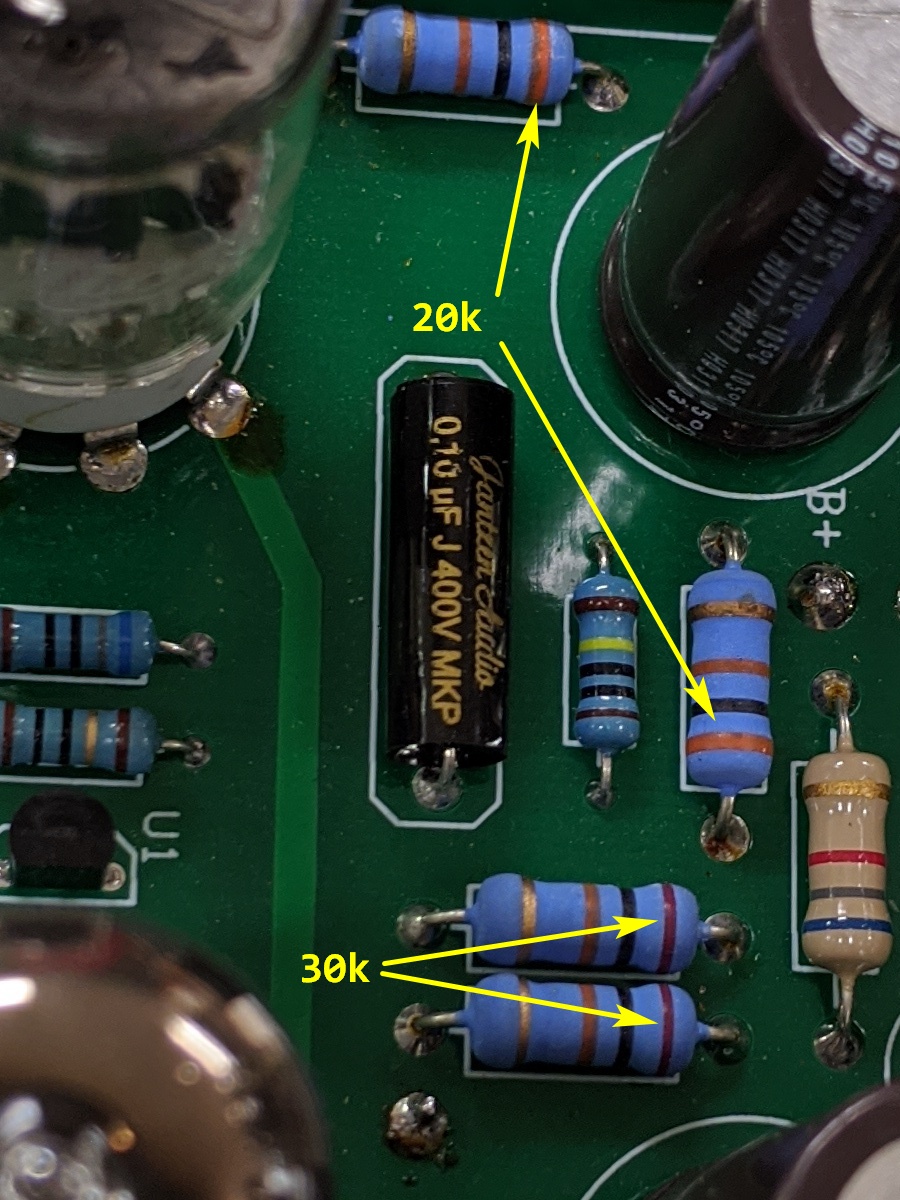
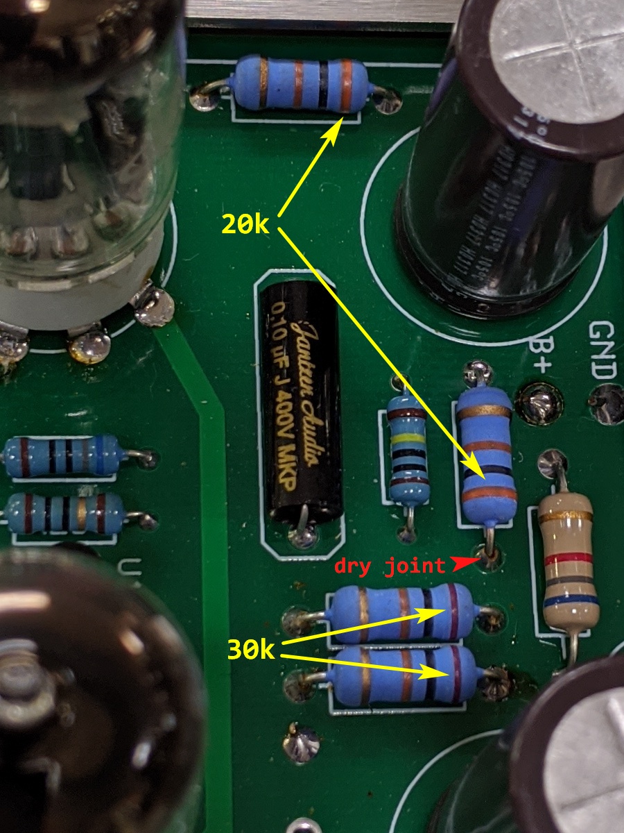
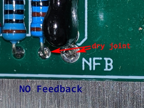

Finally getting the amps on the bench, I find the 20k & 30k resistors are swapped on the driver board! A mere 30% over voltage and current on v7. Think Big Bob will send me new tubes? No? Didn't think so either. The NFB lead on the right amp is a dry joint and failed. Instead of Negative it became NO Feedback. Right Amp: R14 also had a dry joint dropping v6 power. R22-C8 lead popped off upon ABQ removal. Nothing to do but tear this garbage to bits and rework it all like I should have done last year!
Upon inspection, I find the soldering similar to crap Chinese, thus every joint was resoldered. Problems solved.
Without a doubt Mr. Bennihaha Woloss is the absolute worst technician klutz I've come across in 50+ years in HiFi.
Ever since day one, the left amp would occasionally fail to play. Swapping cables and tubes appeared to fix, but problem always re-appeared. Hopefully the last factory defect, the left input jack had an intermittent short!!!
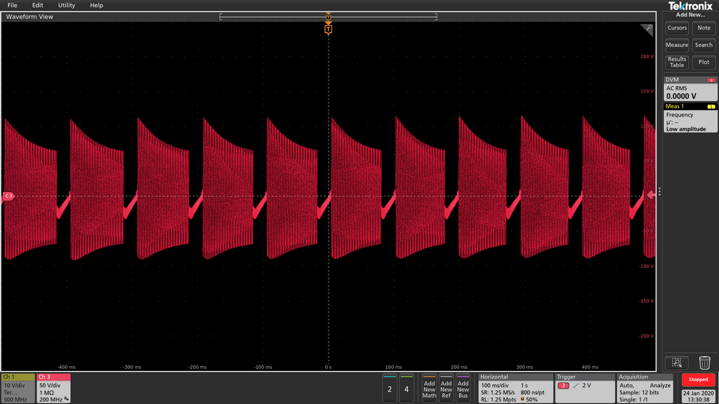
RED plated! now I'm pissed
Poor or non- engineering drives me batshit!
For a few pennies, the design could be 100% stable.
Tubes4HiFi / VTA are either too cheap or incompetent.
In either case, they should up their game!
</rant>
Since the M-125 is basically a rip of the Dynaco 120 / Mk VI, I went back to the originals to see what Latino & co. had screwed up. See Dynaco Transformers for the original 120 and Dynaco Mark VI.
Both the 120 & Mk VI have:
- • power tube plate & g2 snubber resistors
- • local feedback from the -phase U/L g2 tap nested inside the global feedback loop
- • a load across the output transformer 16Ω tap [680ohm;/120 - 620Ω/MkVI]. Mr. Latino admonishes never turn the amplifiers on without a load.

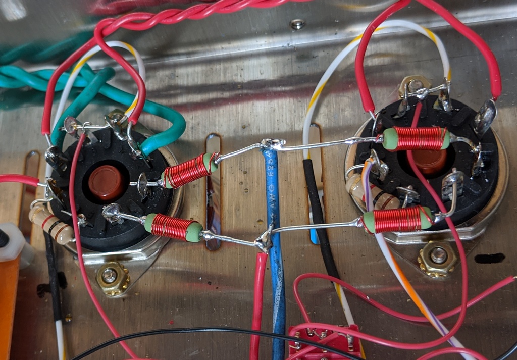
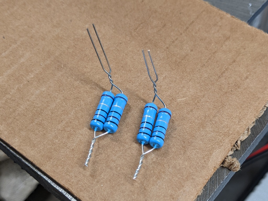
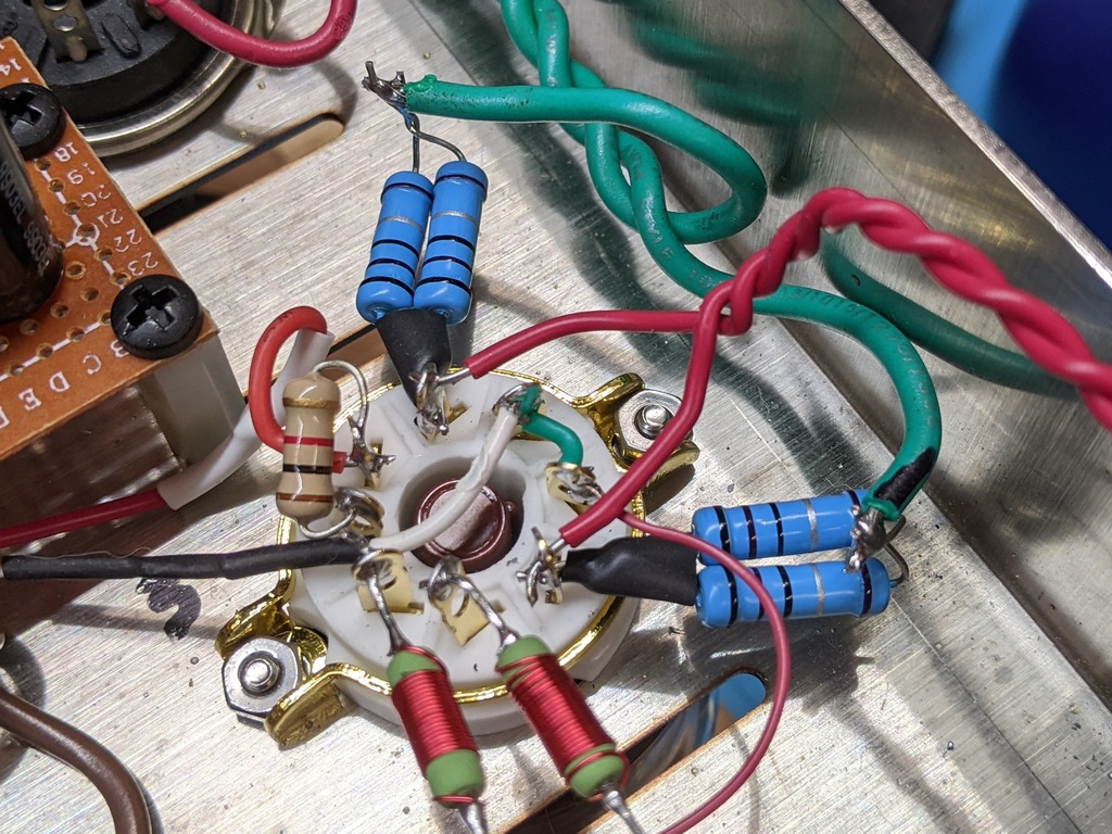
Snubbers
Dynaco amps with parallel output tubes inserted 47Ω at the electrode in output transformer leads to isolate the electrode capacitance and prevent oscillation. Adding snubbers makes the amps 100% stable. NOTE: My amps are UltraLinear ONLY!! Snubber not examined for Triode mode. USE CAUTION if implementing Triode mode. Triode mode w snubbers schematic.
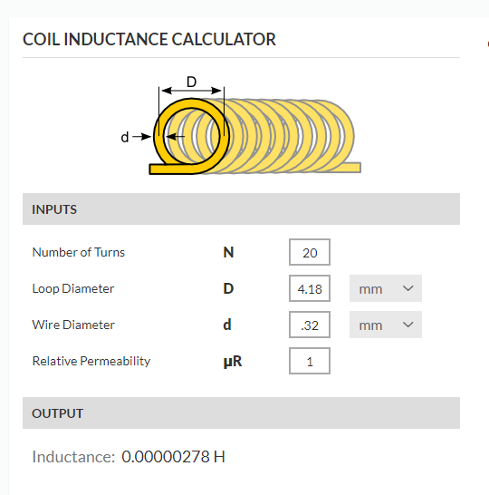
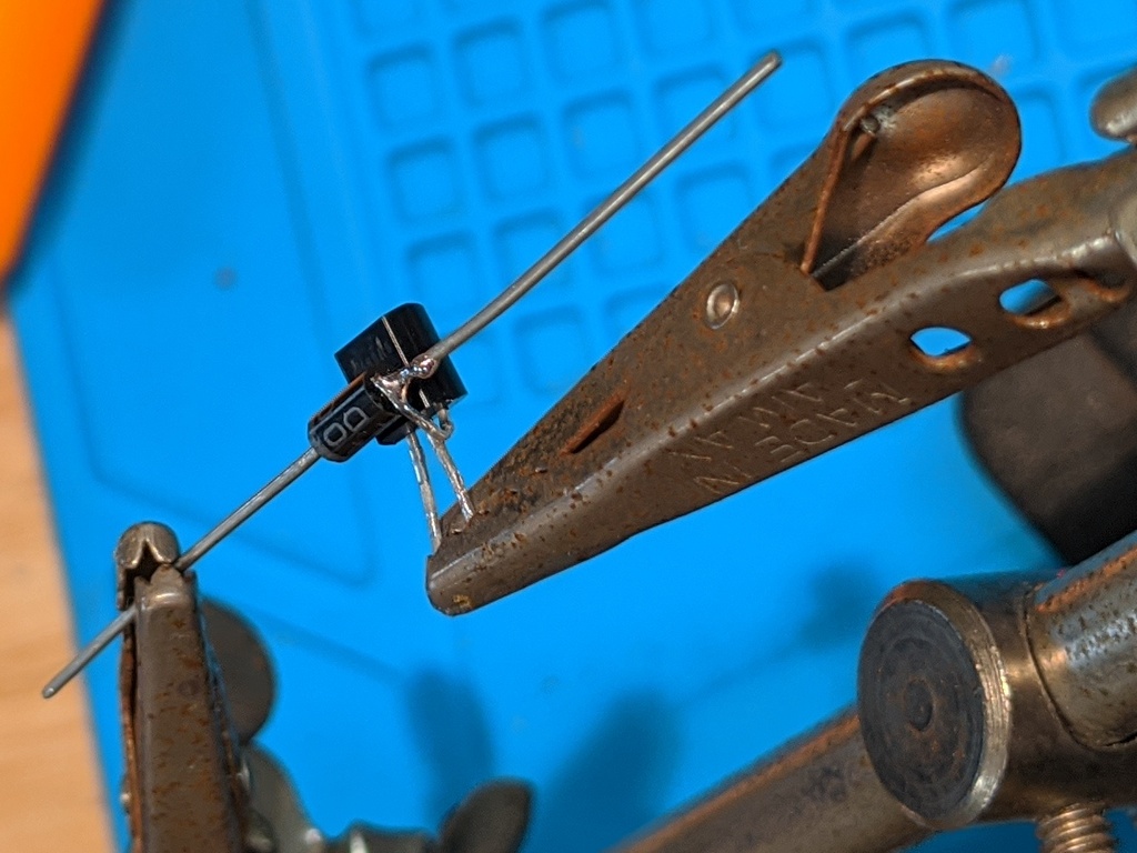
Adding 20-30 turns of 28ga magnet wire around a 2W 47Ω flameproof 700V Carbon Film resistor essentially removes the resistor at audio frequencies. The 2 to 7µH creates an additional pole that is far outside the open loop bandwidth. 28ga chassis wiring ampacity is 1.4A, far more plenty for ≈75mA/KT88. Carbon Film has a negative temperature coefficient so the resistance drops slightly with increased temperature, compensating slightly for the increased OPT positive thermal coefficient. Send me your address and I'll send you ≈15 feet of 28ga magnet wire, more than double enough for 16 0.400 x 0.150 dia 2w resistors.
LM334 Temperature Compensation


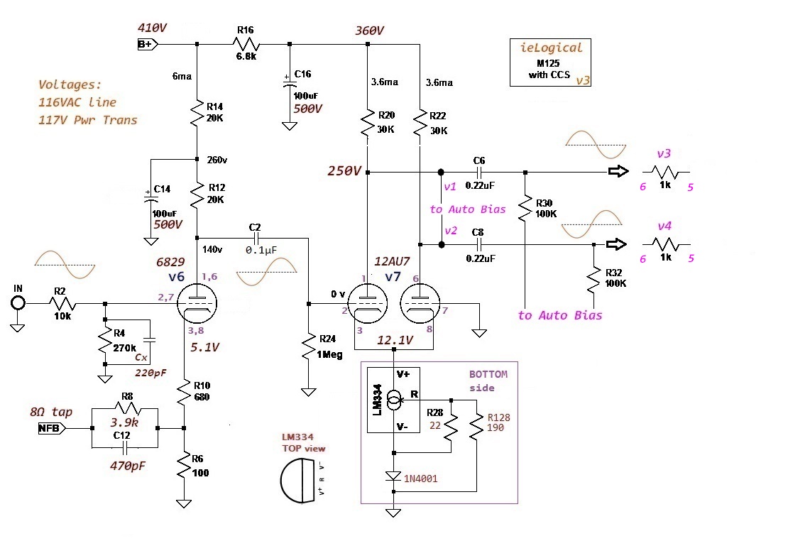

Due to the LM334 instability, the Phase Inverter gain constantly changes, up to ½dB, and as a consequence, the image wanders. The amps never reach equilibrium.
At a minimum, move the LM334 to the underside of the driver board. Note the orientation of the LM334. On the bottom, the LM334 rounded side is toward the transformers. Mounting under the board will prevent some heating by the tubes, helping to stabilize the LM334. The current may not achieve design values quickly as the internal chassis temperature rises more slowly.
For the Temperature Compensated Full Monty:
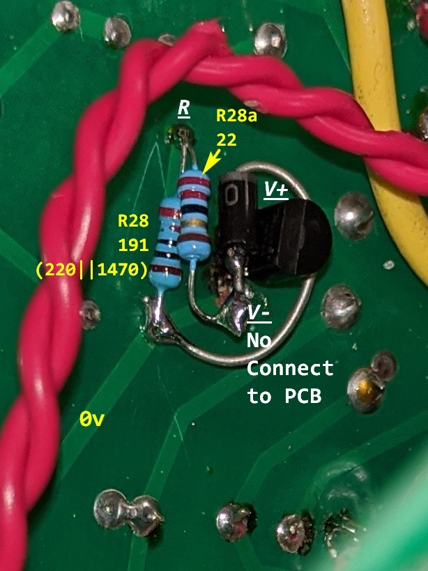
The diode must be as close as possible to the LM334, ideally in contact for maximum compensation effect. Thermal epoxy the two together for maximum tracking [and minimum serviceability]. NOTE: LM334 'V-' terminal DOES NOT CONNECT TO PCB!!!
Since my amps are built, I opted not to cut & strap the driver board. If starting from a bare board, drill the PCB to more firmly mount the parts. ALL CCS parts go on the PCB underside as shown. The 220Ω R28 in the image is trimmed to ≈190Ω with a 1k47 on the component side to compensate for 22Ω rather than an ideal 20.5Ω / 240Ω combination. None the less, the amps are now very stable. Image does not drift. The modified 334 image does not show thermal compound added before buttoning up.[These amps are now officially proto-hacks.]

Check with Bryan for suitability for other VTA / Tubes4HiFi amplifiers. It's a no brainer to install and the improvement is well worth the DoReMi.
final thoughts


One builder expressed concern about clearance between the Big C bank and chassis bottom. With the 0.125" bottom spacers I installed, I calculate the required voltage to jump the gap at about 3.6kV MINIMUM from the exposed metal connections and about 500V higher from the balancing resistors.
We tested several capacitor brands. All capacitor brands tested within 1% after forming. We reviewed a half dozen capacitor manufacturers' balance recommendations, some of which needlessly waste power for close tolerance parts.
It is imperative that balancing resistors are installed as in the SCM.
Recommended practice is to use a pair of resistors per cap pair rather than a single pair with capacitors commoned mid-bank.
The 1µF ESL polypropylene capacitor was removed as it did not enhance the sound. IMO, impedance adjustment is more than hanging a film cap across electrolytics. Performance wise, it made ZERO difference.

• Moving feedback to 8Ω, reduces feedback by 0.707 so R8 is changed to 3.9kΩ. This increases feedback slightly to 4.4dB from 3.9dB, 6dB w v6/6829 & v7/12AU7.
• Changing R8 to 3.9kΩ raises the HF roll-off to 185kHz, probably a bit high given the open loop transformer measurements. Changing to 470pF lowers to 85kHz, a bit less than 96kHz stock. FeedbackGainCalc workbook will allow you to determine feedback.
• 220pF C12 placed across R4 to add input 74kHz Low Pass.
• M-125 has no output transformer "no load" protection. Add 680Ω 5W resistor from 16Ω tap to 0vA for protection in the event of a loudspeaker driver failure, connection loosening, etc. from potentially taking out the OPT.
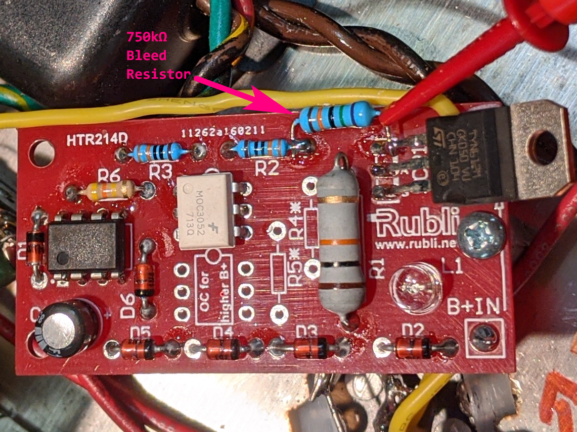
• A century after tubes became commonplace, controversy over the need to delay B+ until electrodes are hot still remains. Thousands of tube articles and opinions, but never proven. If anyone has proof, send me the link! The Rubli HTR214 Soft Start insertion point is after the AuthentiCap 40µF. The HTR214 has no bleed resistor as the manufacturer expects those messing about inside a tube amp to be safe. 24 hours after depowering, the SCR tab is still at 300VDC. Add 750kΩ/1w as shown to bleed the cap in about five minutes.
If using the Weber WS1-T w the Rubli, you can remove the thermistor from the WS1-T. The result is a slightly lower B+ variability with temperature and a cooler environment for the diodes.
Always keep one hand in your pocket until you've verified ALL CAPS ARE DISCHARGED!!!
The life you save is your own.
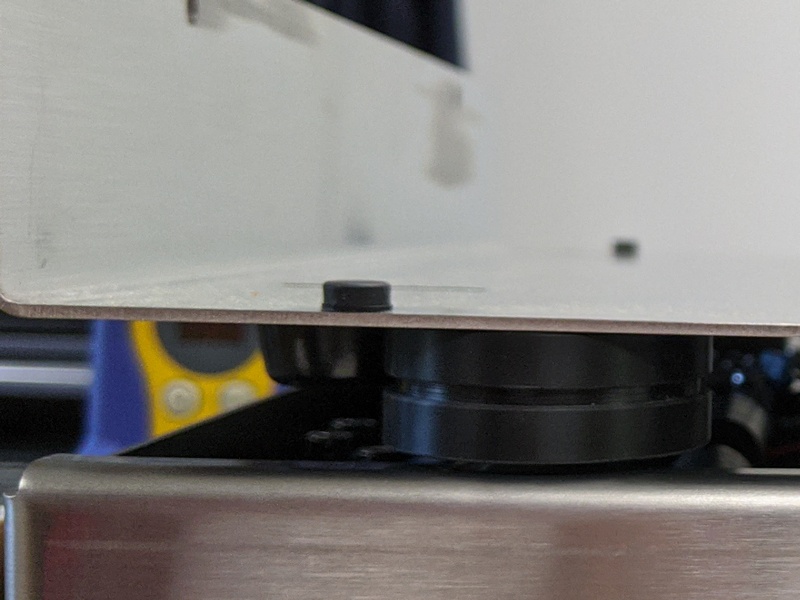
• Before buttoning up, add 6 each 0.25" x 0.125" high round rubber bumper dots, front and rear, to provide a little more chassis ventilation and damping. Centered and 3½ inches either side. Internal temperatures reach ≈40°C after a couple of hours. Not terrible, but 30°C would be more component friendly.
• Optionally add ≈0.062" spacers between top and bottom along the sides to prevent the chassis caving in on the side. My covers provide the necessary support.

like WOW!!!
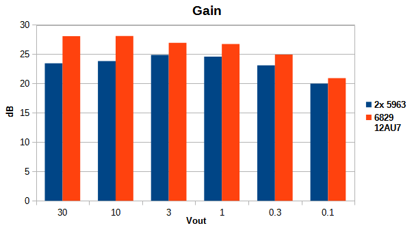
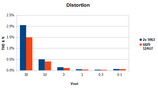
In a tri-amped system, it's a PITA. Something a bit higher gain like a 12AT7 or one with a bit less gain might work. A tube mentioned as a lower gain 12AT7 is the 6829. Like the 5963 it's a computer tube. Tube parameters and Load Line calculations for existing
Sonically, more open and relaxed, especially when the program gets thick and robust. As always, YMMV.
Familiar, decades old recordings reveal heretofore unexperienced detail and transparency, exceeding all expectations. Post listening evaluation, bench performance tests for gain and 1KHz distortion validate the improved sonics.
final Twist

Being of the Not Broke - Don't Fix mindset, I left it alone.
Knowing of course, one day it would bite me...
No biggy to remove and replace the boards with the new one. [Getting the diodes to remain in place it a bit tedious. And they are a might dim for daylight listening.] Left amp went together without a hitch and powered up with bias @ 0.46vdc.
Right amp would not hold bias, hovering around 0.90. After a bit of head scratching, I stuck a meter on the output and found ≈40kHz. Lifting the AB-Q away from the driver removed the oscillation and bias locked on 0.46. WTF? A bit of diddly-fiddling showed that the position of one of the AB-Q/driver wires could set off the oscillation. [Maybe 'splains why Messrs Latino and Mottram quit offering the AB-Q option back in 2019... shortly after they happily sold me mine]. It's not the AB-Q, but the driver that misbehaves.
So, now we have twisted pairs for the bipolar leads to the AB-Q.
[Tube complement updated to ALL JJ from Antique Electronic Supply: 12AY7 driver, ECC802 S/12AU7 Long Plate phase splitter and Apex Matched KT88 Quads.] Not only is it the biggest tube improvement E V E R, but the Apex Matched Quads are incredibly well matched. How do I know? See ieLogical Valve Tester. JJ Tubes purchased from Antique Electronic Supply. If you are getting 2x Quads, be sure to ask for two Quads as closely matched as possible, otherwise you get the first two on the shelf. If Gm varies considerably, gain is off a tad[++] between amps. With AB-Q you can mix the quads, putting one quad in v1/2 and the other quad in v3/4 of both amps. And since I have the tester, I bought 4 each of the JJ 12AY7 and ECC802, matching them into pairs.
The unmatched JJ triodes have as good or better Gm match than almost any “NOS” tubes ever purchased. And UNLIKE NOS, NO GAS! You can use them right away without the need to run them on heaters only for several (150 say some) hours. And some NOS will never deGas! In all honesty, I was quite unprepared for the improvement matched drivers make.
There's just more E V E R Y T H I N G ! YMMV
back 2 BASIC - almost
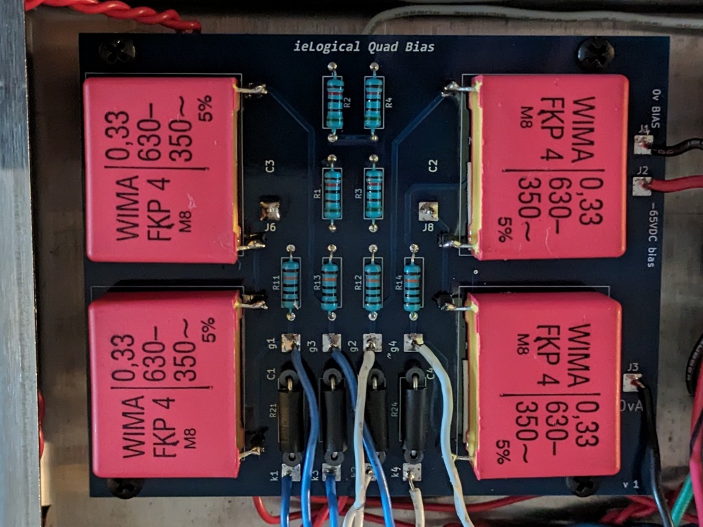


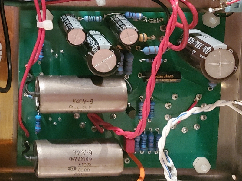
Hence, M-125 Quad Bias Trim with 0.33uF WIMA WIMA FKP 4 Polypropylene caps. They are more transparent and less smearing than the PIOs. Increasing to .33µF flattened square wave response just a tad. Trimmer is a Bournes3339 50kΩ 4 turn, making adjustment a doddle. Recommended to replace VR pots on stock driver board if not using AutoBias.
And since I was waiting for tubes, rather than futz about with a voltmeter to measure bias, a Quad Bias Meter Array. Bias Meter PSU is a regulated 5vdc doubler sourced from the unused 5vac tube diode heater supply. Toggle switch kills display power. Meters not yet fastened to chassis when photo taken...
match This


Note: Two tubes from each quad used in each amp to compensate for the slight mismatch between the quads. Two tubes from each quad go in sockets 1 & 2 and two from the other in sockets 3 & 4. Tubes are indelibly marked to ensure location consistency.
1kHz distortion is under 0.05% @ 12W into 8Ω. Right off the bench, with the changes from the somewhat veiled .22µF PIO caps to .33µF PP, near perfect tube match and possibly fixed (adjustable) vs AutoBias the amps have a new level of transparency and detail.
After about 100 hours tube bias has stabilized, dynamics, inner detail and soundstage are clearly better. Volume level is unchanged, but immediacy is much improved.